Boxcar Underframe Building: TLT 40′ CN Reefers

35241es-CN-TLT-Reefers-with-Underframes-Insalled
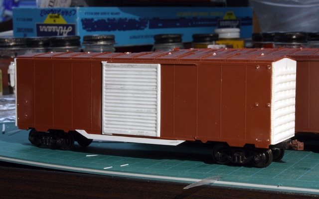
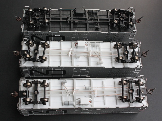
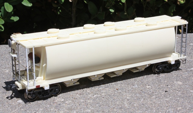
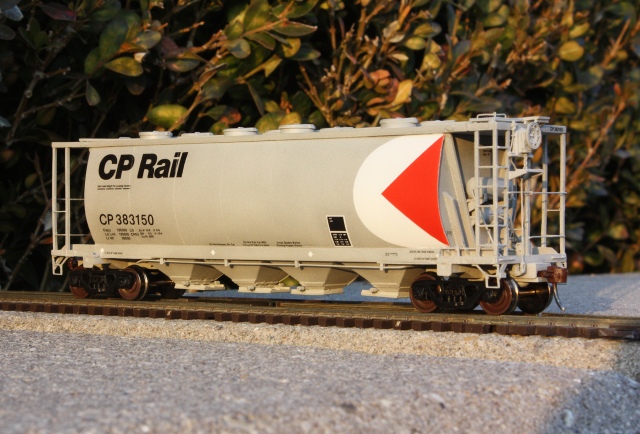
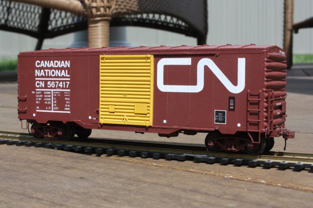
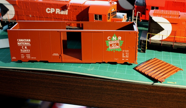
Above: some TLT CN 40′ ice reefer shells that were given a second life, with the addition of some custom underframes!

I recently acquired a few surplus HO-scale True Line Trains 40′ CN refrigerator car shells from a contact that had a few sitting around. The story behind this was years ago TLT originally produced CN reefers in the noodle livery in grey instead of silver, so they had the factory run replacement shells and shipped them out to hobby shops and dealers for replacement. Not all found their way to new owners however, and one can still find some spare shells (either the replacement silver ones, or the original grey ones that were replaced) floating around. Adding underframes to these is an easy way to expand your CN reefer fleet, and put those surplus or replacement shells to good use. This method can also be used to build underframes for other oddball cars and shells you might have sitting around.

40412es-CN_TLT_Reefers
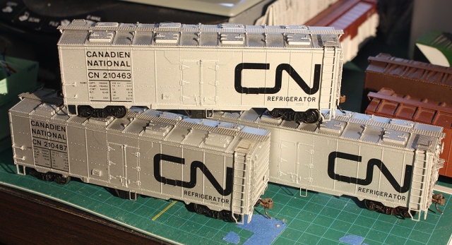
Above: There’s a lame reefer madness joke in here somewhere.

One can put the shells on a different 40′ underframe to put them back into use (like with the modified plug-door TLT car here that used an Athearn “blue box” 40′ boxcar underframe), or one can build their own. Companies like Accurail sell separate plastic underframes that can be utilized, but often bolster spacing and underframe details might not be correct, or need modificatons. As well, many basic underframes aren’t very detailed. The previous TLT reefer build that used a modified Athearn blue-box 40′ boxcar underframe had its drawbacks (the Athearn underframe is not very well detailed, the weight is between the floor and underframe causing a higher ride-height, the cars have poor clip-on coupler pockets, etc).

Prototype Info

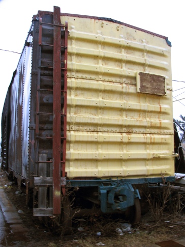
The True Line Trains model represents a steel ice reefer unique to CN (originally designed and built at their own Transcona Shops in Winnipeg MB), of which they owned many that served for decades. Even after ice cooling fell out of favour because of newer mechanically cooled cars, the ice reefers continued in “heater service” use due to their underframe-mounted charcoal-fired heaters. The Canadian Freight Railcar Gallery has photos of the prototypes in the 210000-series, although many were renumbered over time into different groups (e.g. 250000-series cars), and similar cars existed in different groups, with plug doors, or rebuilt with larger doors or door-mounted refrigeration units. The TLT shell as-is represents a common ice-cooled hinged-door variant, but could be modified to represent other cars. Funaro and Camerlengo have released a few different flat resin kits of CN reefers in the past.

Of note: the official colour of the CN noodle cars was silver (the older maple leaf logo cars were grey), but many of the silver ones faded into a dull grey colour with age and dirt buildup, so the incorrect grey bodies could be used to simulate an older weathered car. They often could be found mixed together with fresh silver repaints in service, as is the case here: http://www.railpictures.ca/?attachment_id=33806

The Build

The main parts you’ll need (aside from trucks and couplers) are the underframe components, more specifically the underframe itself and some underframe brake rigging/appliances. I typically use Intermountain 40′ boxcar parts for this, often using either of the following for my projects:

Underframe:
-Intermountain part #P40400-16B (PS1 40′ boxcar underframe) or their #P40700-16A (1937 AAR 40′ boxcar underframe)

Underframe Details:
-Intermountain part #P40400-18A (PS-1 underbody details), or #P40700-18A (1937 AAR boxcar underbody detail set), or Tichy #3013 (AB Brake set)

It’s important to note that we’ll be cutting the frame shorter and replacing the plastic rigging with brass wire, so it doesn’t matter which combination of parts you buy. For this project, I used modified PS-1 underframes and cut out all the brake parts from the PS-1 detail set. But, you can easily use them as-is and together depending on the car you’re building an underframe for (note, the PS1 details are designed to fit the PS1 underframe so buy both together if you’re using the frame as-is, ditto for the 1937 AAR boxcar parts).

Now for a little shout-out: I typically get my boxcar parts, couplers, trucks, etc from online model RR retailer TMR Distributing when I can, as Terry always gets them packaged and mailed out promptly, and his pricing is quite competitive – especially when it comes finding and buying parts from US manufacturers in Canada.

The Underframe:

The floor was made from a piece of flat 0.040″ sheet styrene, cut about 14.1cm x 3.3cm (41′ by 9′ 1/2″ scale feet). It was given scribes with an X-acto knife blade to simulate the visible floor slats from below. A modified Intermountain 40′ PS1 boxcar underframe was then glued on. To get the correct truck/bolster spacing, the Intermountain PS1 underframe was shortened about 4mm to bring the bolster spacing to about 10.7cm (31 scale feet). Some of the support ribs underneath had bits of styrene glued to their ends to extend them to the edge of the floor. A few thin strips of 0.020″ styrene were cut to run between the bolsters and glued into place.

33027es - CN 210463 custom underframe and spare for 22xxxx rebuildAbove: a bare frame and floor (modified and shortened Intermountain frame on a styrene floor), next to a completely detailed frame.

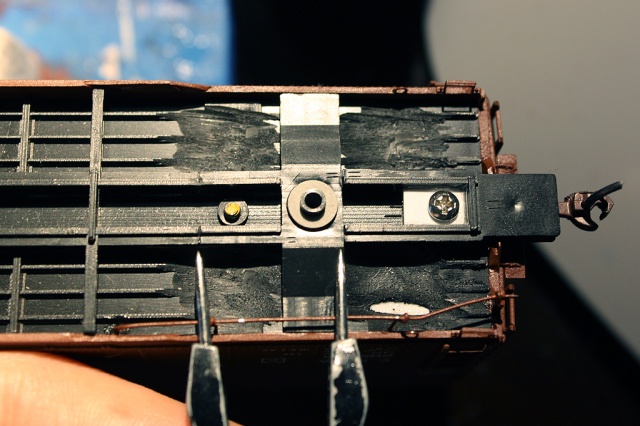
On top of the floor (inside the body) some 0.010″ styrene bits were glued around the edges to get the body to sit right. To re-enforce the ends of the floor where the couplers and coupler boxes would be mounted, some extra 0.040″ styrene sheet was glued to increase the thickness over the bolster and coupler pocket area, and two thick 0.040″ styrene strips were glued upright along the length of the floor to offer extra rigidity to the underframe, and braced with smaller bits. Once dry, holes were marked, drilled and tapped for 2-56 screws to mount Kadee coupler boxes (your preference for draft gear may differ, but a Kadee #232, #242 box or some #175 semi-scale draft gear does the trick nicely). This was all tested at various times to make sure the custom underframes would fit the TLT reefer bodies.

33029es-Underframes-tops
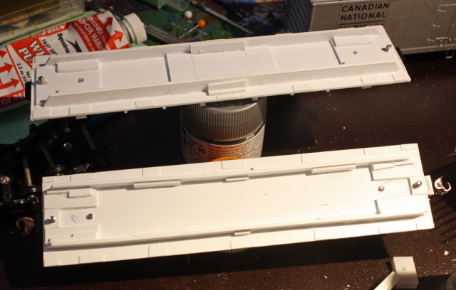
Above: some quickie re-enforcement on top of the underframe floor, using 0.040″ styrene above the coupler areas and along the length of the floor. Most of the extra bits and pieces to brace them came from the styrene scraps box. Also note the 0.010″ shims added to the edges to adjust the body height.

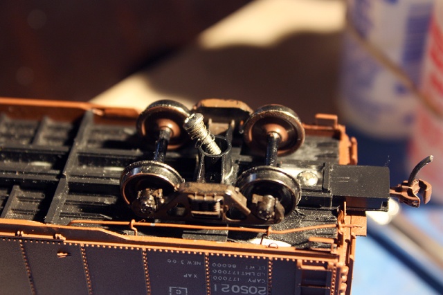
Once the underframe was glued to the floor, some spare round sprue bits were glued into the Intermountain bolster holes (one could use styrene rod too), drilled and tapped for 2-56 screws.

For the underframe brake rigging, one could use either an Intermountain 1937 AAR boxcar brake rigging set and shorten it to fit the underframe, or just salvage the brake rigging components (triple valve, air reservoir, brake cylinder, etc) from that or a PS-1 set, and replace all the rigging with 0.0125 or 0.015″ wire (which is what I ended up doing). As an alternative, components from Tichy’s #3013 AB brake set can also be used.

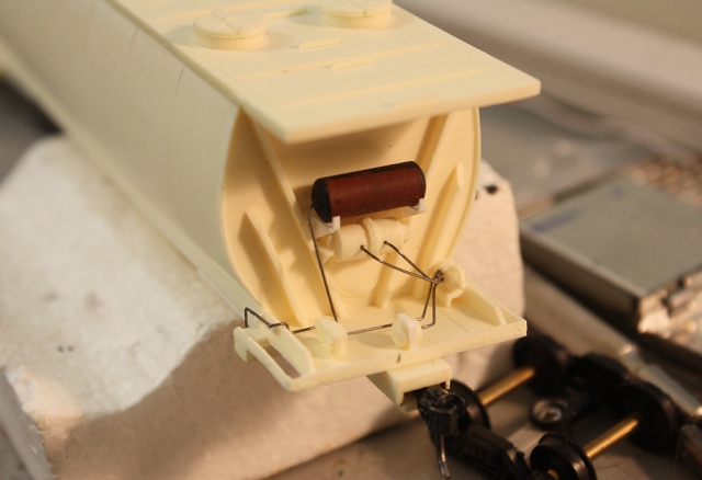
After plugging and filling all the holes on the Intermountain underframe, it was time to add parts. First I drilled some holes into the sides of the triple valve and air reservoir  and ran two short lengths of wire between them. Then, they were glued to the underframe by mounting them on some 0.040″ styrene blocks to get them the right height. Two thin 0.010″ strips of styrene were wrapped around the ends of the reservoir tank to represent the mounting brackets. The brake cylinder was then drilled through so a wire from the rigging could be run through it (one could add a small length of chain here between the cylinder’s pointed end and rigging bars if they desire, but for simplicity it was left off), and another styrene block built up to mount it on at the correct height. Then I drilled out the two rigging bars/arms underneath and cut and glued the appropriate lengths of wire into them. Some U brackets were bent from wire to hold the rigging up and glued into holes drilled into the frame. Holes were also drilled in the underframe near the trucks for the ends of the brake rigging to mount into.  The brake wheel chain rigging from the Intermountain set was then mounted at the B-end alongside the coupler box.

35242es - Underframes ready for paint
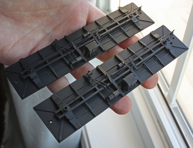
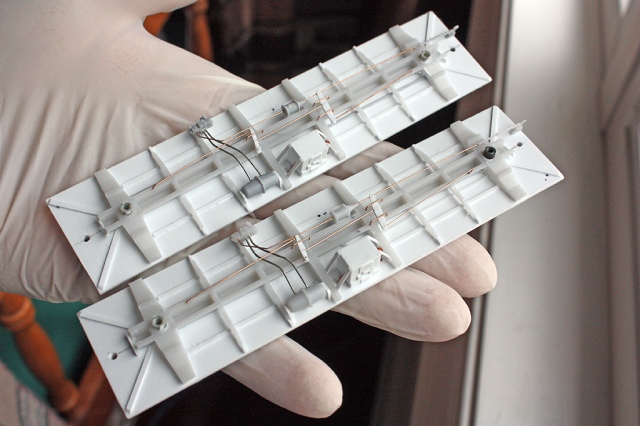
Above: Detailed underframes, showing the custom brake rigging fabricated from wire, styrene, and bits of the Intermountain brake detail sets.

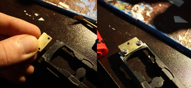
The charcoal-fired heater unit box mounted underneath was scratchbuilt from styrene (it’s a simple box measuring 9 x 9 x 7 mm) and detailed with styrene bits. Some wires were bent and glued into holes on the sides of the box to represent piping running from it to the car. Once the heater unit was glued on, strips of 0.010″ styrene were added and gently bent to represent the bracing. This was all mounted in the middle of the underframe, on the “right” side of the car (assuming the A-end is the front, and the B-end with brake wheel is the rear).

35240es - CN 251729 210487 210463 custom underframes (bot to top)
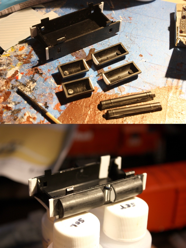
Above: one completed and painted underframe (top), with two uncompleted ones (center & bottom) and most of the parts test-fit.

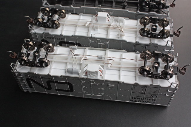
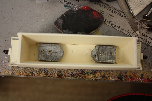
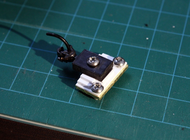
For painting, all the trucks, couplers and coupler boxes were removed and the underframes cleaned, then the bottom given a coat of Tamiya Fine Surface Primer grey or TLT primer grey (depending on when I finished and painted them). After drying a day or two, the underframes were then given a few coats of Badger Engine Black, and sealed with some clear (Model Master semi-gloss clear acrylic is ideal, although one can add weathering followed by a coat of clear flat). The trucks (some spare Proto 2000 Bettendorf-style solid/friction bearing trucks with 33″ wheelsets) and Kadee couplers were painted (flat black for the wheel faces, and Rapido Old Rust for the couplers) and reinstalled. Weight was then added to the top to get the cars up to around 4 ounces, and the completed underframes were set aside for now.

35243es - CN 251729 and 210487 (top) custom underframesAbove: two completed underframes, all painted and ready for couplers, trucks, etc to be re-installed.

33033bexs-Custom-reefer-underframe-completed
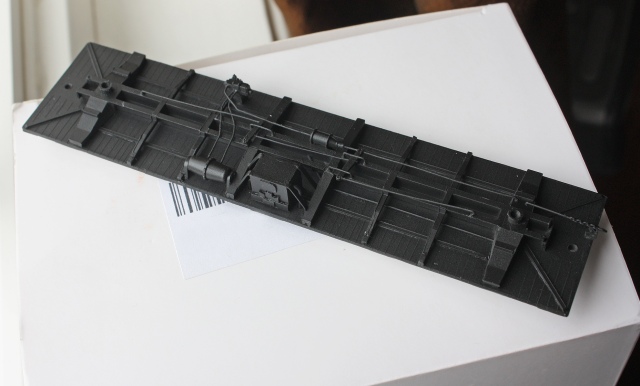
Above: Yet another underframe. I think I built about four of these, with one held in reserve for another shell waiting on a future project.

40414es - Reefer custom underframe
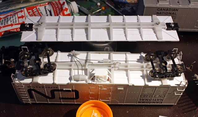
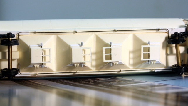
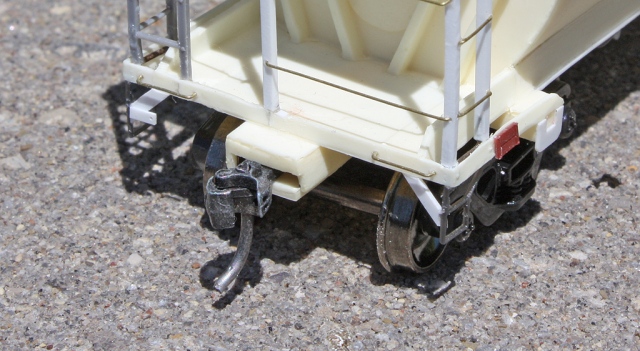
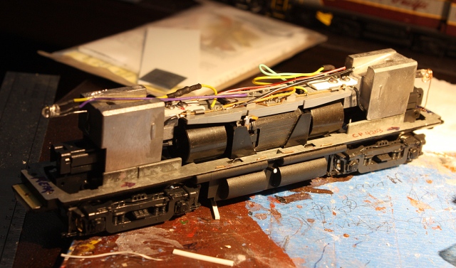
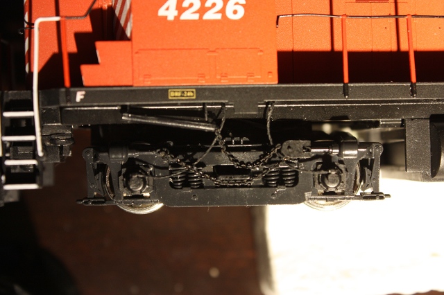
Above: Underside view of a completed underframe installed in a TLT reefer shell.

Body Modifications

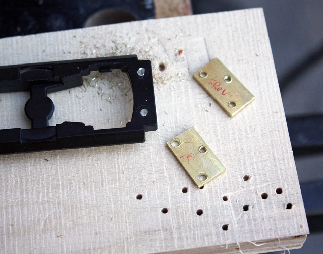
For the reefer’s B-end brake rigging, this needed to be replicated (on the TLT models, the rigging linkage that went to the brakewheel housing was glued to the underframe, and not included with the bodies). The linkage was made with a length of 0.0125″ brass wire, looped around a short length of Details West chain (40 links per inch), with a wire eyebolt at the end of that. A hole was drilled at the bottom of the brakewheel housing, the new rigging fed into the end brake walkeay, and the eyebolt end of the rigging glued in. The bottom end of the wire was bent up and glued into a hole drilled into the bottom of the end of the body, so that the bottom of the rigging would meet up with the underframe’s rigging linkage. It was then painted Tamiya Flat Aluminum, except the bent up part at the bottom that was painted black to disguise it.

40413es - Reefer end
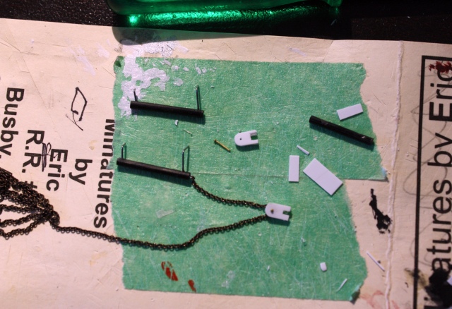
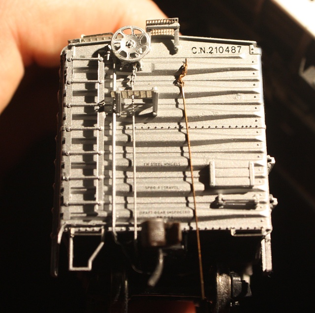
Above: a new brake rigging rod from brakewheel to underframe is already painted and installed on this car, shown with an unpainted example made from a small length of 0.0125″ wire and short length of chain (on right). Tack boards also lowered, and old mounting holes patched and touched up with silver paint.

At this time, I also re-located the end tack boards on the shell from upper to lower positions, by carefully cutting them off the body and gluing them lower on the ends, based on prototype photos. The old holes were then filled with putty, sanded smooth, and touching up with a special mix of aluminum paint (see below). CN did relocate the side tack boards from the right to the left side of the doors to avoid interfering with the large noodle logos applied, but since the side tack boards on the model were cast-on to the body, this step was skipped for simplicity’s sake.

40411es-CN251729-reefer-renumbered
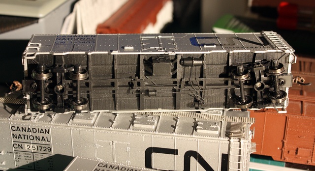
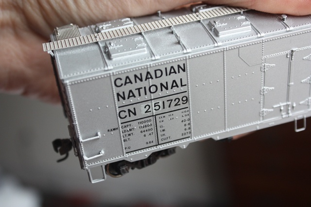
Above: this car was carefully renumbered using both of the methods described below. The old number was painted over with a custom silver mix to match the body colour, and “1729” decalled over as if it was part of the original roadnumber. Then, a “patch mix” of silver with a bit of white/grey was added to give it a noticeable patch, and the “25” was added to represent the car being renumbered to a different series.

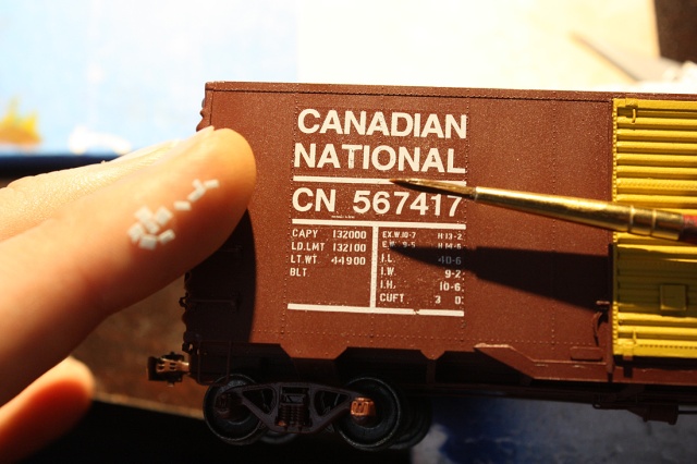
Two of the reefer models were also renumbered at this time to represent different groups of cars, however, the TLT factory lettering was difficult to remove without damaging the paint underneath. To get around this issue, a custom batch of paint was carefully mixed to match the TLT paint and hand-painted on. Tamiya’s “Flat Aluminum” silver was used, with a touch of black to darken the colour slightly until it was a satisfactory match to the shade of the silver factory paint. One can either carefully scrape off the old numbers with a sharp X-acto blade and touch up the area with paint, or paint over the old numbers and renumber the car with Black Cat decals.

Now, this method was to just renumber a car without visible patching. CN did patch its reefers to renumber them into different groups (e.g. a 21xxxx car to a 25xxxx car) and the paint didn’t always match. For a car with a visible patch, some silver was mixed with a bit of grey or white to get more noticeable number patch, and then decalled over with new numbers.

Posted in Uncategorized | 5 Comments

CP 290856 Double Door Boxcar

IMG_6745es-CP_290856_double_door_boxcar(s-clean)
Above: CP 290856 all complete and ready to haul some lumber.

CP and CN were both rebuilding groups of boxcar on in the 1960’s and 1970’s to handle increase in demand for lumber during the housing boom around that time. It involved either rebuilding old double-door 40′ boxcars (many of which were used for transporting automobiles prior to the widescale introduction of the autorack), or converting old obsolete single-door cars into double door cars for easier lumber loading. This car was part of a group of the latter: an early 1950’s single-door 40′ boxcar (with 10’6″ inside height, often referred to as the 1944 AAR design) with single 6′ doors rebuilt with a 6′ and 8′ door combo in 1973, part of the series of cars in the CP 290000-290724 and 290725-291024 groups (see roster info here). Other groups of single door cars CP rebuilt had been done with double 6′ doors in the 298000-series.

This HO-scale model was built very much the same way as CP 298008 was, the main difference being the different door combo, longer door tracks because of it, and the later more common paint scheme variation (the initial/early CP Action Red/Yellow/Green livery applied on boxcars had a black sill, which was dropped by CP for repaints) .

As always, it’s always best to start out with a few good photographs of the prototype for modeling reference. Some photos of cars from this series can be found on the Canadian Freight Railcar Gallery.

Sourcing A Model

The ideal starting point for one of these builds is Intermountain’s undecorated kit 41899 (10’6″ IH 40′ Modified AAR (1944) boxcar, with 4/4 ends and 8-rug ladders) or stripping a decorated 46800-series model (this one started off as a factory-painted Erie
Lackawanna car). One could also use a Branchline Blueprint 40′ boxcar. A new diagonal-panel Intermountain roof was sourced from the parts box to replace the kit’s raised-panel roof (roofs, ends, and doors could vary depending on what the prototype was rebuilt from). The stock Improved Dreadnaught Ends (IDE) from the car were kept.

33567bexs-EL70749
Above: When undecorated models are out of stock or hard to find, an decorated model for an unpopular railway is a good option for a “core” to rebuild. The disadvantage is having to strip the paint and risking damage to details during their removal, but an advantage is you get metal wheelsets and couplers included (IMRC leaves them out of their undecorated kits).

Since a decorated car was being used, most of the main details were removed and the paint stripped by letting the model soak in 99% isopropyl alcohol (fresh alcohol works better than old/stale) and some scrubbing with an old toothbrush. With an undecorated car, you can just skip this step and start the build.

Body Modifications

Starting off, the old lower door tracks and details along the sill were shaved off with an X-acto #17 chisel blade, and new sills were cut from 0.010″ sheet styrene (roughly 11.9cm x 4mm) and glued on. Bits of 0.020″ styrene were glued behind to re-enforce the sills so they wouldn’t flex or distort when handling. New lower door tracks were cut from 0.020″ styrene and upper door track extensions from 0.010″ styrene and glued in place (some putty and sanded was required to get the new upper tracks to blend in with the existing ones).

The doors were then installed, using one Intermountain 6′ Youngstown door and one modified Accurail 8′ Youngstown door that’s not an exact match, but close to the prototype with the later style door hardware at the bottom (the thick center ribs were trimmed thinner, and cast-on tack boards chiseled off in favour of separate parts). Details added to the doors were the large and small tack boards, styrene bits for the lifting tabs at the top and door track tabs, that were added at the upper and lower edges of the doors. A center door latch between the two doors was scratchbuilt, and finally a piece of styrene added on the top door track to replicate the tab over where the doors meet.

For the re-enforcement gussets around the door edges added during rebuilding, 0.010″ styrene was cut into triangular shapes to match prototype photos, sanded a bit thinner, and glued in place. Since the gussets extended under the bottoms of the lower
door tracks, additional rectangular pieces were added below, with and etched with a sharp pointed pin to create the holes in the prototype gussets. The door stops had been carefully shaved off earlier, and were re-added at the ends of the new door tracks.

IMG_6072bexs-CP_290856_boxcar_unpainted
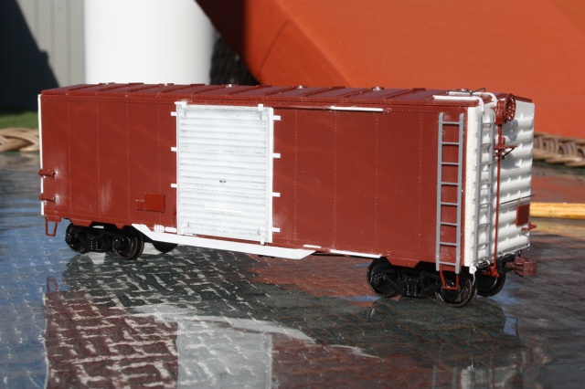
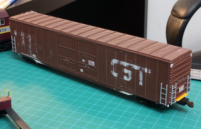
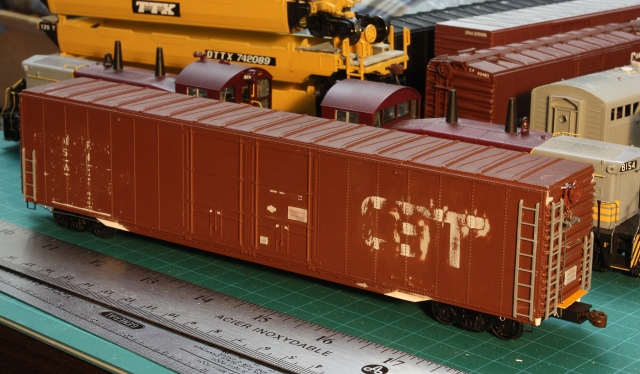
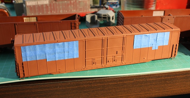
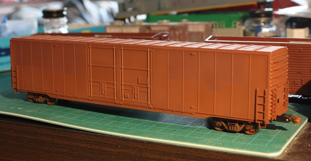
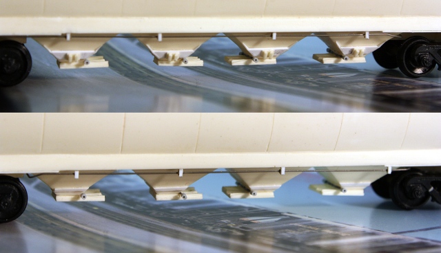
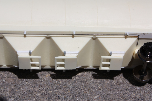
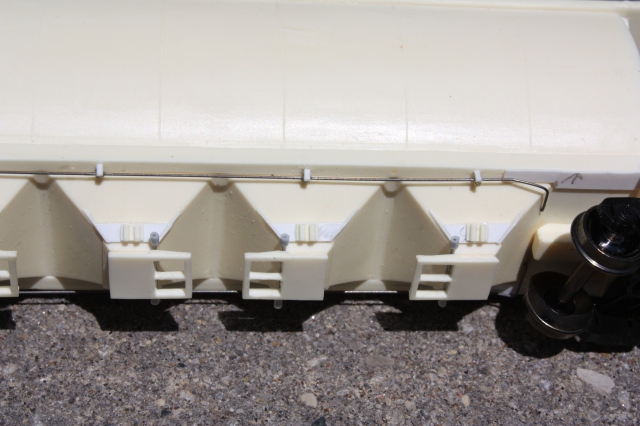
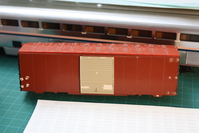
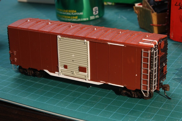
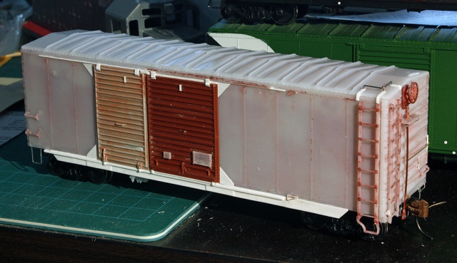
Above: this photo shows most of the main detailing work complete. Note gussets added around the door openings (by the door corners) during rebuild to re-enforce the car. The new deeper sill running the length of the car was added for similar reasons.

IMG_6077bexsmall-CP290856-boxcar
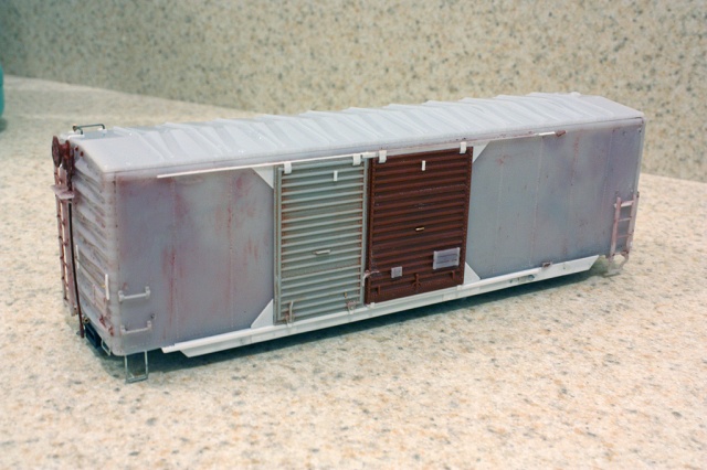
Above: a quick look at the other side of the car with most of the detailing complete. The trucks and couplers have been removed in preparation for to washing and priming.

Since this model was “modernized” by removal of the roofwalk (as CP and CN did to many boxcars in the late 60’s and beyond), no roofwalk was added and the A-end ladders were both cut down to half-height, with extra mounting holes on the body filled. The B-end ladders were always left full-height to access the high brake wheel (CP and CN didn’t bother to relocate them lower) and some thin strips of 0.010″ styrene were added on the roof for the B-end corner grab mounts. The grab itself was made from 0.012″ wire with an eyebolt.

Continuing the detailing process, the Intermountain 8-rug ladders that came with the car were added back to the model (the side ladders had attached stirrup steps at the bottom, but the end ladders typically had the attached stirrups removed when rebuilt). End and corner grab irons were added to the ends and side corners where required, and side stirrup steps added under them (the sill tab in the Intermountain body here was cut off, holes were drilled, and new stirrups made of wire were glued into the bottom of the car).

The B-end brakewheel rigging and platform details (minus the retainer valve details) were added in the usual position. New end railings on both ends (another “modernized” feature CP and CN added) built using thin styrene 0.010″ bits for the mounting brackets spanning the ribs (3 on the A-end, 2 on the B-end), and 0.0125″ wire for the railings. Tack boards were also mounted to both ends in the lower postion according to photos. NBW bits can be added near the tops of the ends to represent where the end roofwalk support brackets were removed.

IMG_6073bexs-CP290856-boxcar-ends-combined
Above: the A-end and B-ends showing some of the detailing added. Note the lower ladders on the A-end, and different end railings depending on each end of the car.

Tiny bits of styrene were cut and drilled for the cut lever brackets, and glued to the lower parts of the end ladders. Eyebolts were drilled and installed near the bottom rib above the coupler for the cut levers (bent out of 0.0125″ wire, but installed later after painting).

Underframe Details

The stock coupler boxes were glued on, drilled and tapped for 2-56 screws. The lids had a hole countersunk into them for using flush-fitting flat-head screws. Some may wish to replace the Intermountain coupler boxes/draft gear with scale or semi-scale parts from Kadee or Details West (note, most of CP’s 40′ boxcars had standard non-cushioned draft gear, except for some specially equipped cars).

As this car has deeper sills that tend to hide the underframe, the stock Intermountain underframe detailing set was installed. The train air lines (or “glad hands”) by the couplers at each end were glued to the sides of the coupler boxes inset near the sill, allowing the lines to flex a bit instead of breaking off if a mis-couple happens or a coupler comes into contact with them. At this point, Intermountain 33″ smooth-back wheels with Accurail Bettendorf trucks (stock on most recent Intermountain offerings) and Kadee #58 couplers were “allocated” to the model (to be installed after painting). The couplers were painted with Rapido Old Rust paint, the wheel faces with Tamiya Flat Black, and the axles and rear wheel surfaces with Rapido Grimy Black.

Painting and Decalling

After a wash to remove any hand-oils or fingerprints, the car was given a few light coats of Tamiya Fine Surface Primer grey and left to dry for a few days.

IMG_6206bexs-CP_290856_boxcar_painted
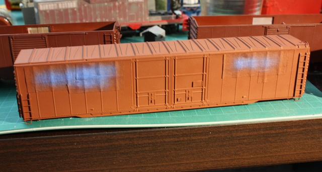
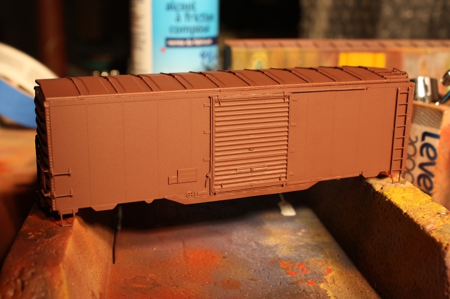
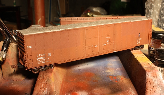
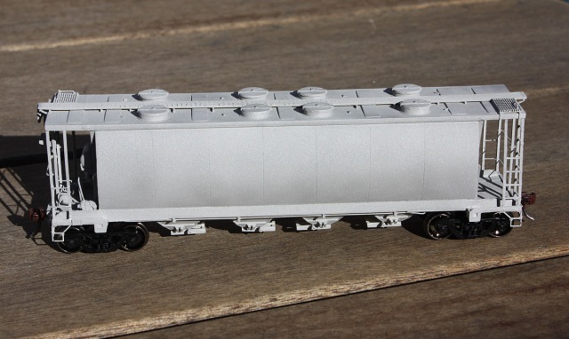
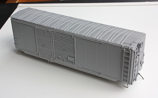
Above: Primed and ready to go. Note the loose roof: it’s easier to handle while painting without the roof, and it’s best to glue it on at the end after weighting and adding any extra weight.

After that, any small imperfections were corrected with putty and sanding as-needed. The car was then given a few light coats of (discontinued) True Line Trains Action Red (TruColor Paint makes a very close CP Action Red of their own), and the TLT stencil white and warm black of the multimark sprayed on according to the handy multimark painting how-to.  The car was then given a coat or two of thinned TLT Gloss Glaze (same basic thing as Testors Model Master Gloss acrylic).

An old set of out of production CDS decals were used for all the main detailing including numbers, lettering and data, with various Black Cat, Highball and Microscale water-slide decals used any extra bits. Final touch-ups were made as needed (including the addition of cut levers), and the model was then sealed with clear again. The aforementioned couplers and trucks were then added, the car weighted, and the roof glued on.

IMG_6738bs-CP290856-side
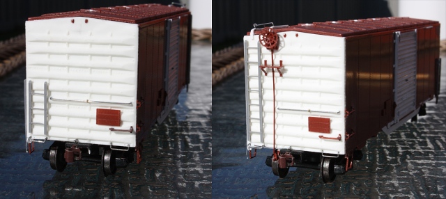
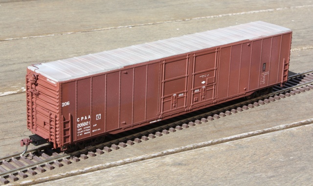
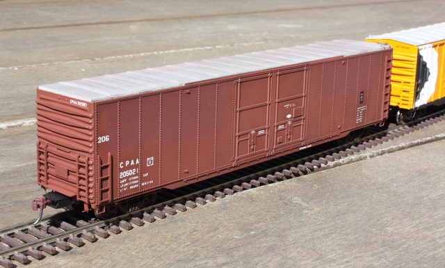
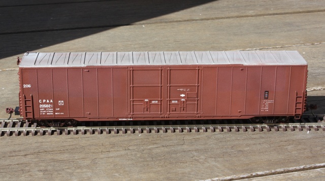
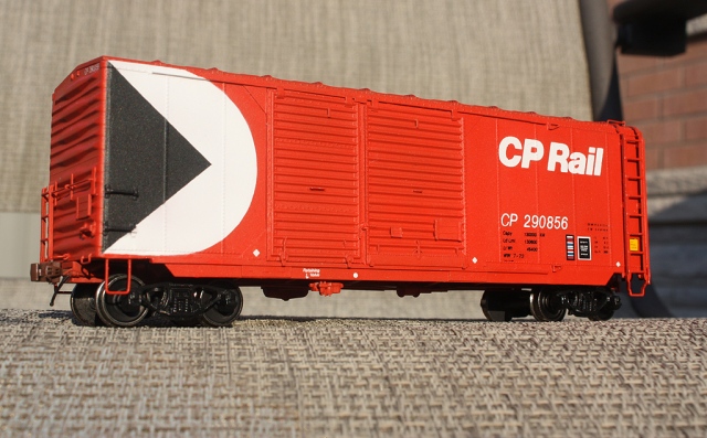
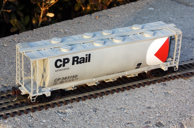
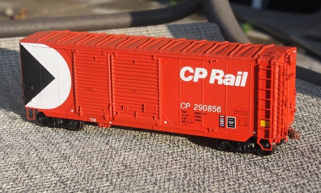
Above: CP 290856 completed, showing the left-hand side near the B-end.

IMG_6742bexs-CP290856-Aend
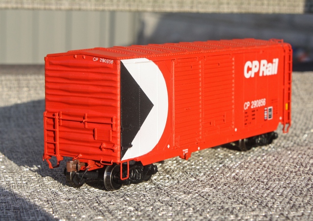
Above: CP 290856 completed, giving a better look at the A-end detailing.

IMG_6741bexs-CP_290856
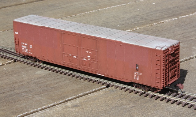
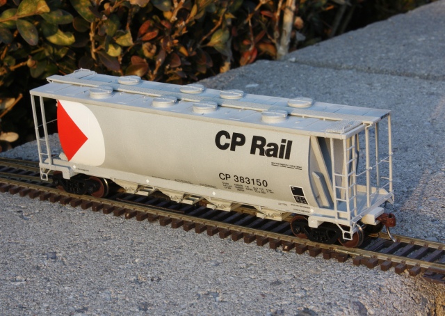
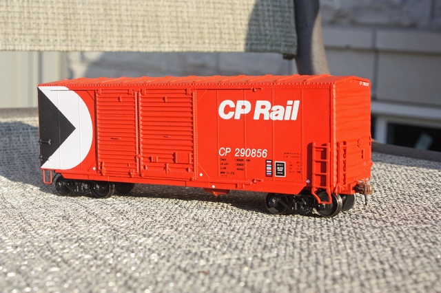
Above: CP 290856 completed, showing off the right-hand side of the car.

IMG_6746bs-CP298008-290856
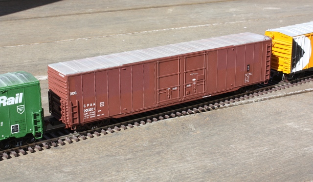
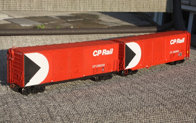
Above: CP 290856 completed, with previously-built double door boxcar 298008. Note the differences in paint scheme and door sizes.

Posted in Uncategorized | Leave a comment

CP Rail Aluminum “Tank” Covered Hopper – Sylvan Scale Models build

23869bexs - CP 383150 covered hopper (desk).jpg
A-lum-in-um? Al-umin-e-um? Aluminumumum?

This is the big kahuna. This is the final level boss battle. Anyone can slap a resin kit together and call it done, but if you can build one of these cars good, and I mean good, you can probably tackle 99% of the kits out there. The most challenging model I’ve built yet is the Sylvan Scale Models CP Aluminum “tank” covered hopper (yes, more challenging than the Funaro & Camerlengo flat resin CP “minibox” kit, or any Kaslo resin shell kit). An early design of the common teardrop or round-sided covered hopper cars all over North America today, they were built starting in the late 1950’s for CP and CN out of aluminum, and later evolved into a steel sided design.

One of these puppies makes assembling a Kaslo GP9RM shell seem like putting together a P2K mill gondola kit: sure there’s a lot of bits, but you have most if not all of the parts you need included (and they look and fit reasonably well), prototype photos are easy to find, and you don’t have to go ahead and do anything like scratchbuilding major components like end cages, or digging through tonnes of books and crawling the web for elusive reference photos. All challenges associated with this model that can make you want to put it back in the box and never speak hide nor hair of it again.

Some Background Info:

In 1959, Alcan and CN jointly developed a new type of hopper, one of a tubular design made of aluminum with rounded sides and no centre sill. It was also slightly shorter than the current rectangular “slab side” hoppers CN & CP were using, but of the same 3000cuft capacity. Made in 4 and 8 hatch versions, they ultimately lead to the later steel design cars, and the fully cylindrical cars purchased en-masse by many Canadian outfits. These earlier cars were given the nickname “tank hoppers”, and CN and CP both purchased aluminum versions made by MLW, Marine Industries and National Steel Car (CP did go on to buy the similar looking 3400cuft steel cars (painted black), but CN only bought the earlier aluminum ones). There were minor variations between the orders and builders, as well as CN vs CP cars (end air brake tanks, side tabbed brake piping mounting, skirting between the bays, re-enforcements welded to the side sills by the RR’s later on). Data suggests CP’s were off-roster by the late 80’s. CN’s lasted a bit longer, and they still had a few kicking around a few years back in OCS idler car or sand service (53390 series).

Photos of the CP cars themselves are difficult to find, but you can pick them out in trains because of their silver colour, compared to the plentiful steel cars that were painted black. Information suggests two uses they saw were hauling nepheline syenite out of the mines in Nephton and Blue Mountain, Ontario off the Havelock Sub, and in potash service out west. They frequently went south of the 49th parallel (two reference photos show them in Illinois, and Dallas TX hauling syenite. Other photos I’ve seen show them in Toronto ON (possibly being spotted at Redpath Sugar) and at Nelson BC.

Strutting its stuff in Illinois:
http://www.canadianfreightcargallery.ca/cgi-bin/image.pl?i=cp383202&o=cprail

This one’s probably in eastern Ontario somewhere:
http://www.images.technomuses.ca/searchpf.php?id=226384&lang=en

Common cargos hauled in this style of round-hatch covered hopper would be potash, sand, cement, fertilizer, sugar, salt, and nepheline syenite.

The Model:

Many pieces of oddball equipment are only available in brass or as resin kits, if at all. This model is one of Sylvan Scale Model’s out of production resin “tank hopper” kits, of which a few different CN & CP versions were made.

Back in March 2015, a friend alerted me to someone selling a pair of the unbuilt hopper kits on eBay for a reasonable price. 2 were available, so he buys one (a CN 4-hatch aluminum car) and I buy one (a CP 8-hatch aluminum car).

I had originally wanted to do one of the more plentiful black steel CP hoppers (CP’s aluminum ones were only aluminum, with markings/logos applied to them), but the kit was for the aluminum version and there is notable capacity difference between the two (3000cuft aluminum vs 3400 cuft steel) so one can’t substitute one type for the other. As well, It’s very finding good reference photos of CP’s aluminum cars – I’ve only found a grand total of 5 good photos, and only one in the multimark livery (but about half to a dozen photos of the CN cars…)

19680bes-CPTankHopper.jpg
This is how many kits start off, and how many kits end up – sitting in their boxes either unbuilt, or half-built and put back out of frustration. The decals were included, but trucks and couplers are usually separate (the trucks here were a pair of spares slipped in by me).

After all the parts were verified to be present and included, they were given a cleaning using Sylvan’s resin prep solution to remove any leftover casting residue from the parts.

19670bes-WashedBits.jpg
The parts were given a quick washing in some resin prep solution, then rinsed off and set to dry. It’s usually easier to leave the small bits together and trim the flash off later, lest any tiny pieces get lost or washed down the drain.

Now the fun begins…

On this model there was some unfortunate warping on the body. In addition to the roof casting being a bit warped both length-wise and width-wise, one of the sides of the carbody was cast thicker than normal, and sort of bulged out. Due to the thickness of the sides, there was no fixing this error with hot water and firm pressure (as one would with thinner parts). After a good amount of sanding and getting not very far I said to hell with it, and just lined up the slightly warped edge of the roof with the warped side of the carbody, marked them, and glued them together like that later on when the roof was done. Not entirely impressed with that, but it’s not overly noticeable unless you’re really looking for it (the second car I bought was a little better in this regard).

20018es-WarpedCarbody.jpg
Bulging/warped resin bodies, Dan is not impressed.

After all that was sorted out, some basic assembly took place: the underframe piece with the bays was fitted and glued in, along with the two truck bolster/coupler box/frame members at the ends. Since this is resin, you can’t use regular modeling cement and must use some kind of cyanoacrylate adhesive (CA glue) or super glue. Don’t stick your fingers together!

The weight box was raided and the scale was brought out bring the car up to basic NMRA weight specs. The weights inside were spare bits cut off Proto 2000 GP9’s that received chop noses over the years. Since I wasn’t sure how well supergluing the weights to the slippery resin floor inside would hold up over time, I also drilled through the weights and into the floor, tapped the holes, and put in some long 2-56 screws in. A few bulk packs from China can be bought relatively cheaply, leaving one with literally tonnes of screws to burn.

20047s-Weights.jpg

Weights, always important, especially in a car that’s going to be “sealed” so no more weight can be added.

The roof was then positioned accurately and superglued on (I used pieces of styrene glued on the underside of the roof to help work out exact positioning before gluing the whole thing on) and then the roof hatches were glued on (with bits of styrene added between to simulate the hatch stops).

End Brake Piping:

It was decided to start building the end brake piping setup before tackling the end cages. This is where the trouble, guesstimating and excessive digging came into play, as photos of these cars are difficult to find, much less photos giving a good view of the end details. In all my travels over “teh internets”, I’ve been able to locate few good photos of these CP aluminum cars, and fewer still that give a good view of the brake piping setup behind the end cages (one low-resolution photo gives a poor view of the B-end setup). The CN cars are similar but again: few good photos, and there were differences in the air tanks, brake piping and rigging setups.

The instructions were of little to no help for this, as they didn’t match the single end photo of the CP aluminum car I dug up showing the B-end, and included no brake piping instructions or diagram. I think two of the end variation illustrations shown were actually mixed up too.

Working off what photos I had, I was able to put together some semblance of a brake system on the B-end bent from 0.015″ wire, including building a larger custom air tank for the top from a piece of spare styrene sprue that was rounded off, and make bigger mounts out of styrene for both air tanks. There were a few guesstimations made here and there.

20132bes-B-End.jpg 
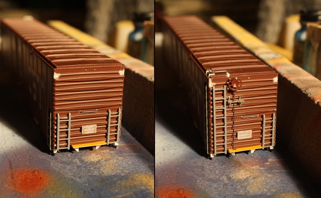
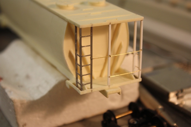
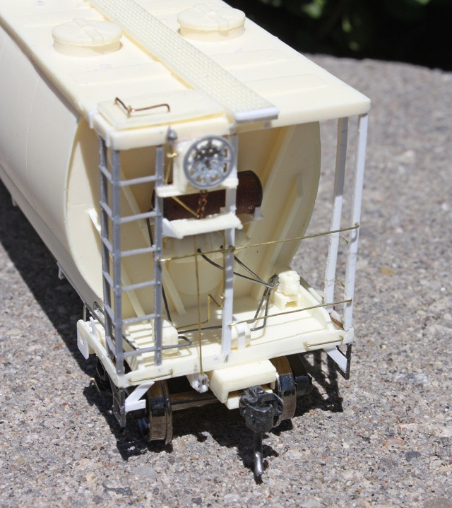
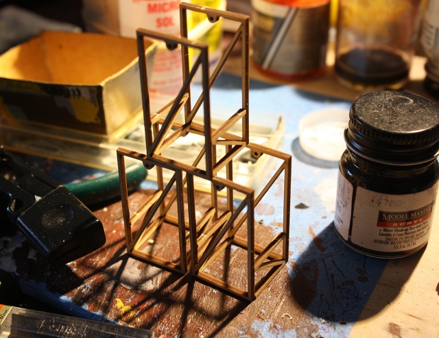
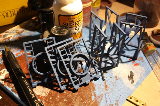
Above shows the basic brake piping setup, a few more pipes need to be added before adding the end cages (see later photos). Most of the small resin brake system bits included were used.

IMG_5116e.jpg
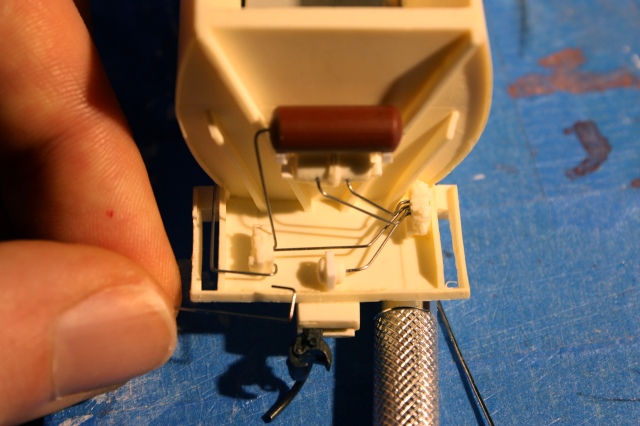
All the end piping detail is applied at the B-end, the A-end is basically bare.

End Cages:

Turning my attention to the A-end, I found the stock resin end bars included to build the end cages to be too fragile, and the tiny styrene rungs also included not very durable. Initially I decided to drill out the resin bars for new brass wire rugs, but after installing them and not all the rugs lining up correctly, and having one bar break, they were all removed and it was back to the drawing board.

(I also found a little discrepancy in the Sylvan instructions: the CP aluminum cars only had one bar in the middle on both the end cage assemblies (slightly offset to the left), as opposed to two on the B-end of the steel cars (A-end had only one, offset to the right). The Sylvan instructions show two in the middle for all variations, and probably assume both ends are the same. Again, easy to miss all this due to lack of reference photos).

The solution in the end was to make new end cages using close-enough Tichy #3033 end ladders, brass 0.010″ wire and styrene 0.040″ x 0.040″ rod. The Tichy ladder rug spacing was a hair tighter than the prototypes, but otherwise a pretty good match. The ladders and rods all had holes drilled in the top and bottom ends for 0.015″ wire, which fit into holes I drilled in the car’s roof and floor ends, to make them more durable in the event something were to happen. The styrene rod is a bit more flexible and stronger than the somewhat brittle resin bars with the kit.

20136bs-EndBar.jpg
Drilling out both ends of the end bars and ladders for wire re-enforcement to be inserted at the tops and bottoms.

25695bexs-EndLadderCages.jpg
Various ladders and bars for making the end cages. The bottom ladders had one bar cut off, and would be butted against the bar of the latters at the top, to form the corner ladder assemblies. Note the bits of wire placed in holes drilled in the bottoms of the bars, which will fit into holes drilled into the bottom platforms of the car. Markings were made to show where to drill for the handrails/grab irons, and everything drilled before installation.

20146bs-Cages.jpg
The bars on the side cage setup (non-ladder corners) that go above the stirrup steps were looped together at the bottom with wire, glued inside the frame above the stirrup area.

25697 - End railing installation.jpg
Ladders and bars installed, applying the end railings made from 0.010″ brass wire.

20147bs-SideGrabInstall.jpg
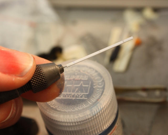
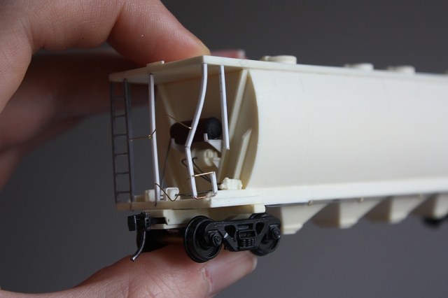
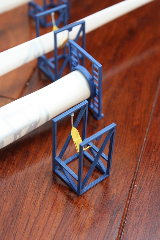
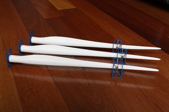
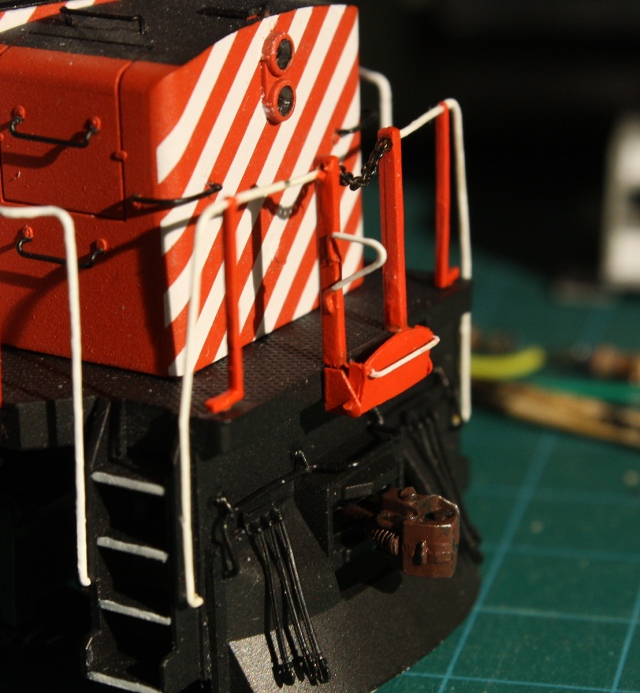
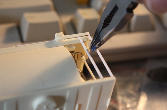
Slipping some brass wire grabs in the non-ladder corners (all the holes were measured and drilled before installing the end cages, easier to drill them that way)

20134bs-EndRoof.jpg
Parts were test-fit, and then holes were marked and drilled in the top of the roof and into the tops of the bars and ladders allowed bits of wire to be inserted and glued in, strengthening the end cage assemblies. They would be filled with putty and sanded smooth later.

20137s-EndCages.jpg
Basic end cage assembly work done. This is the A-end (non-brake end), which is bare of brake details and piping.

(One interesting A-end variation on the aluminum and steel tank hoppers was CP (probably in the 70’s) torched off the upper 2 rugs of the side ladders and the corresponding half of the top roof grab (but left the adjoining end ladder and top grab intact). Probably a modernization effort similar to cutting down full height boxcar ladders, but leaving the end one intact for roof hatch access. See photo above. No rugs on the B-ends were removed).

20148bs-SideDamageFall.jpg
B-end cages built up, with a little boo-boo after a fall that had to be rectified. Mistakes happen!

After the end cages were assembled, it was time to move on to detailing the brake wheel area and the brake rigging around the B-end. The stock brake wheel mount, walkway and Tichy brake wheel were used, but new longer platform supports were made from styrene. The brake rigging linkage was built using A-line chain and 0.010″ brass wire. The bottom rigging rocker was fabricated from styrene (CP’s aluminum cars had it mounted under the frame, CN’s had it mounted just above). Some extra brake piping was also run up the side of the car from underneath to inside the cages for the retaining valve. Again, the lack of photos means some of this had to be guesstimated.
20260bes-CPAluminumHopperBend.jpg
That should do it.

20263bes-CPAluminumHopperBend.jpg
Happily all this was only required on the one end (B-end).

The roofwalk was installed, wire roof corner grabs were drilled and inserted at the corners, and some roofwalk retaining straps made of styrene strip (and bent down the roof sides) were added. The roofwalk was a little short, so I extended it with bits of styrene, and installed some end supports (not shown however – I must have forgotten and installed them later prior to painting).

Underframe:

All is not over yet – some work is required on the underframe!

21343bes-CP383xxxbottomhatches.jpg
Piping, bays, detailed bits, etc!

The long brake piping on each end was bent from 0.015″ steel wire according to photos, and holes were drilled in the underside of the carbody near the trucks for the ends to fit into. The piping supports along the sides were made from bending pieces of 0.010″ brass wire around the piping twice, drilling holes on the underside edges, and inserting/gluing both ends of the wire into the holes. Bits of 0.010″ styrene were then glued in front of the supports, hiding the wire loops (on earlier aluminum hoppers like 383068 linked above, these extend a bit up the frame sides, but on later ones like 383202 they’re mounted fully underneath) . The wire loops give the piping a more durable mounting, and as many modelers grab freight cars by the underside edges, will hold up better to regular handling. The Sylvan kit instructions suggest making these piping supports out of paper bits (yes, really, check the instructions), which probably won’t hold up that well over time.

Some 0.010″ styrene was added to make the trim around the bottoms of the bays on both sides. This detail differed from side to side, and photos suggest the left sides of the bays were more bare, while the right side had some additional bay bracing (added from styrene bits) and the shaker brackets (which were added from the kit). These aluminum hoppers also had additional skirting between the bays, but the photo of the CP Rail livery car I was building appears to have had them removed (torched out for better underframe/gate access?), and this kit version doesn’t include them either, so it wasn’t a concern (the skirting should be added for CP script cars and CN though. I think the CN Sylvan cars have the skirting cast into the underframe part).

21342bes-CP383xxxbottomhatches.jpg
Brake piping as viewed from the sides.

The bottom discharge assemblies were glued on the bay bottoms, and the gate opening bars/cranks were made from 0.015″ wire glued on the inside, with bits of styrene sprue drilled and glued on the ends.

22474.JPG
Left side bays closeup.

22475.JPG
Right side bays closeup.

Also note, thin strips of 0.010″ styrene were glued to the underframe undersides near the truck bolsters (visible above the trucks). These appear to have been re-enforcement gussets or something similar welded to the underframes by the bolsters (CN did something similar with their cars too – always work from photos!).

22462bexs-End Details.jpg
Closeup of some of the extra end details added.

Other small bits added to the ends/underframe were the stirrup steps (Tichy parts, included in the kit), stirrup step bracings and coupler lift bar mount (made from thin styrene bits), U-shaped bolster plates on the bolster ends above the trucks (cut from thin 0.010″ styrene sheet), end grab irons, and two small tack boards on the bottom frame near the bolsters on both sides (Branchline parts).

Ready for Painting

Some photos of the “undecorated” detailed model, almost ready for the paint shop.

22460bxs - CP 383150 tank covered hopper.jpg
B-end, right side of the car.

22461bxs - CP 383150 tank covered hopper.jpg
A-end, right side of the car.

22458bxs - CP 383150 tank covered hopper.jpg
B-end, left side of the car.

22459bxs - CP 383150 tank covered hopper.jpg
Yep, yet another shot of all the B-end detail. The A-end is basically like this but devoid of all the details except end cages and handrails/grabs, as shown in another of the above photos.

The trucks and couplers were removed , and the car was given a wash in soapy water and a good rinse to remove any hand oils prior to painting.

Paint Shop Time

The car was given a good coat of grey primer in preparation for the silver. These cars were unpainted bare aluminum, and usually weren’t very shiny (more of a dull silver and often having a dull weathered look). I mixed a custom batch of Tamiya flat aluminum, medium grey, flat white and thinned with all with distilled water for airbrushing. After spraying on a few coats (pay attention to the nooks and crannies in the end areas), the car was clear-coated with True Line Trains Gloss Glaze acrylic paint (although TLT has discontinued its paints, Testor’s Model Master gloss and semi-gloss clear acyrlic is similar. Information suggests that TLT paint was done by Testors/Pollyscale, and is basically Pollyscale paint made to Canadian colours).

22882bxs - CP 383150 silver painted tank covered hopper.jpg
“We can has silver!”  Painted, needs some clear, and then decal time.

The multimarks were then masked and sprayed using my usual method (described here). A note that on black and silver cars, CP painted the triangle red instead of black.

The Sylvan CP Rail livery decals that came with the kit were a bit on the thick side (in terms of the decal film – even after multiple coats of clear, you can still pick out the film glint), so Microscale decals from their generic CP Rail freight car set were substituted when possible (for the larger lettering and roadnumbers) and the Sylvan decals were used for most of the data. If one is doing a script car, I’d probably advise finding a Microscale set (their silver pressure unloading covered hopper set might work). The reflective triangle decals came from a Black Cat CP boxcar set, and the COTS block from a Highball set. Once all the Microset/sol setting solutions were dry, everything was sealed with some more clear.

And…huzzah:

23847bes - CP 383150 finished, 408pm.jpg
Ooooooo!”

23841bes - CP 383150 finished, 406pm.jpg
“Aaaaaah!”

23849bes - CP 383150 finished, 409pm.jpg
“Work that catwalk, girl!”

Final details applied/reapplied: the appropriate trucks were Walthers 70-ton (ASF?) trucks, borrowed off one of their Canadian bulkhead flatcars, with Athearn 33″ metal wheelsets painted a rust colour (you might have noticed some earlier photos taken have a pair of generic Accurail trucks in their place, used as temporary “shop trucks” during the build process). Kadee #58 couplers were also painted and installed at the ends. Everything was drilled and tapped for 2-56 3/16″ screws (the resin is a bit soft, so for a more durable screw hole you can drill out the holes larger, superglue a piece of styrene rod or sprue that fits in, and drill and tap the middle of the styrene rod. I’ve had to do this with a few cars whose truck screw holes were stripped out in the past, but coupler boxes can be a bit shallower and harder to do).

Reviewing some of this now, it seems I forgot the end air hoses and cut levers. But not to worry, I’ll get around adding them to CP 383150 when I add them on a sister 383xxx car currently under construction (to be done in the script livery)…

29122bxs - Sylvan Resin Tank Covered Hoppers.jpg
Cloning: it’s not just for sheep anymore.

Posted in Uncategorized | 4 Comments

AMB Wind Turbine Blade, Cone & Nacelle Flatcar Loads

26486s-Wind_Turbine_Blades_Batch2.jpg
Have wings, now to call for the crane.

With many places embracing wind power as an environmentally friendly way of generating electricity, the large and bulky wind turbine blade wings, parts and sections need to be shipped from the manufacturers to erection sites. Since they’re often made up of many loads and sections that need to be transported and assembled, trucking wouldn’t be the most efficient method for transporting them long distances. No, most of the time you’ll see them being transported by rail on long flatcars, using special cradles, bracket and supports to hold them upright. To model this, there’s a few options. AMB (American Model Builders) makes resin-cast kits for wind turbine blades, centre cones, and nacelles (the large square mount the cone is fixed to). There are also a few 3D-printed offerings out there.

This build will be on doing up a few of AMB’s HO-scale kits for flatcar loads. Specifically, #218 Turbine Blade and Blocking 3-Pack, and #217 Nacelle and Cone with Blocking.

Parts Cleanup and Prep Work

Before starting, clean off all parts with a resin cleaner to remove any casting release residue on the part (some parts did seem a bit slippery when unpackaged). I used Sylvan resin prep, which is basically repackaged orange Zep cleaner, but some people use dish detergent, etc.

The wing castings are generally well done. There are a few areas that need cleanup work however: along the rounded edge of the blade (opposite the wing edge) both edges of some of the castings don’t meet together flush, and need to be sanded down and filled with putty for a smooth round surface. A few of the wings have small bubbled areas from the casting process, one came with some casting “gashes” along the side, and the bottom flat round end (casting end?) can have bubbles that needed to be filled with putty and sanded smooth. You’ll probably find yourself doing this a few times during the painting process, as it’s often difficult to see all the imperfections in the unpainted resin surface.

Two of the three wing tips were slightly warped, in both 3-pack sets. I’m thinking this is because of how the 3-packs of wings are packed: they come staggered in a plastic sleeved bag that’s folded into the box, effectively stacking the wing tips and ends over each other. The heavier wing ends sitting on the thinner wing tips for a long period of time warps the tips and gives them “memory” – even after running them under very hot water and sitting them under a weight bent in the opposite direction, they eventually returned to their original bent orientations. But then again, some of the blades in real life do look curved, so…

25443es-BladesPaintShop.jpg
It’s painting time.

Painting Notes

Casting cleanup aside, once all that was done, they were given another soapy wash to get rid of any skin oils from handling, and the painting process began. For resin I like to shy away from the usual acrylics and use Tamiya’s white Fine Surface Primer – it’s both durable and dries smooth. A warning though – ideally spray outside or can get “buzzed” from the very strong vapors. And, building up thin coats is best: applying too much too quickly or too thick can cause the paint to run, and then you’ll have to wait for it to cure before sanding the area smooth to continue painting. I gave my wings and nacelle/cone sets a few coats of FSP in each painting “session”, and between extra patching and sanding had about 3 “sessions” to build up a nice thick white finish on each part (it’s easy to spy yellow-ish areas that need more paint to cover the resin better). Let the painted parts fully dry out for about 2-3 days before giving a quick coat of clear (I used Model Master semi-gloss). Take your time, don’t rush, and the result will be well worth it.

25342s-PaintingTurbineBlades.jpg
Some outdoor spraying on a warm morning.

One tip for painting the wings: use the hole drilled for mounting them on the base support, and drill and run a screw through a round bottle cap to firmly attach it to the end. This gives you a nice “handle” to use when spraying and lets you rotate the wing to get even coverage. It also lets you sit the wing upright (on the bottle cap) between spraying to avoid setting it down sideways and marring any paint that’s not dry. This method is also good for painting the cones.

26340es-BladePaintEndCaps.jpg
Mounting the blades to a bottle cap lets you easily rotate the blade as you spray on the paint, without having to touch the blade. Then the cab can be removed later, and the end painted white.

Building the Wing Blade Supports

The wing tip support frames are made of laser-cut wood and appear to match photos of one version of supports found online (there are many different wing support and base support versions out there). Once cut out, they were assembled with CA glue and airbrushed with blue (I used Pollyscale GTW blue) before a light coat of clear. The support slings however are made of a very thin clear plastic and the flexible part in the middle where the wing sits is very fragile – on two of mine it split in this area. I re-enforced it here with a strip of thin 0.020″ styrene bent to fit into the bottom. The bottom of the sling was painted Rapido CP Diesel Yellow, and the chain bits were painted Tamiya XF-16 Flat Aluminum (the whole sling was then coated with Microscale clear flat). The small brass nails for connecting the saddle ends to the frame tops were cut shorter, CA’ed in place, and touched up with matching paint.

25540es-BladeSupports.jpg
Wing blade tip support frames glued together.

25634s-BladeSupports.jpg
Painted and ready for blade loads.

The wing base supports are made of a very sturdy resin, but the quality of the castings and resin is a bit rough (injected plastic pieces would probably be better). Nevertheless, after being cleaned up with a sharp X-Acto knife, the laser-cut wood block “feet” were glued on with CA and a hole drilled in the upper circular part for mounting a screw that would hold the wing on. One may need to add small bits of styrene to the inside of the cup to get the wing sitting in the support so that they’re perpendicular to each other. The end supports were also given a coat of Pollyscale GTW blue and clear coated. A 2-56 hole was drilled and tapped in each of the blades (important: the sharp edge of the blade on these ones must face up – check orientation before you drill your holes in the ends of the blades) and a 2-56 5/16″ screw was firmly screwed in each to join the blade to the base support. I then filled the screw hole with white glue and painted it blue to match the base. This hides the screw, and makes or easy removal if needed (just pick out the white glue, and unscrew).

25624es-BladeSupports.jpg
Wing base supports and tip supports painted blue, ready for more work. Holes drilled for the 2-56 screw that will secure the blade in, and the fragile (unpainted) clear slings have been re-enforced at the bottom with styrene.
26607es-EndSupport
End support with blade installed. Screw head filled with with white glue and painted over to blend in to end bulkhead area.

Once everything was dry, the painted wing blades were brought out and they were all assembled:

25630s-TurbineBladeBatch1.jpg
Wing blades all painted up and installed on supports, ready for flat car loading.
26485s-Wind_Turbine_Blades_Batch2.jpg
25631s-BladesBatch1.jpg

Cones and Nacelles

The cone and nacelle castings were relatively well done, but a few exhibit mold lines from casting in the surfaces. The rectangular nacelle in particular needs cleanup on the rear end from the casting process: the edges need to be sanded down to match the rest of the casting, and a new seam line needs to be etched/filed across the top to connect both side seams. Two of the three I’ve dealt with also have lots of casting bubbles in this area that need to be filled with putty and sanded smooth. This rough casting area on the cone is on the bottom, so one doesn’t need to worry about the finish as much. As with the wings, they were painted with Tamiya FSP and given a coat of clear.

The cone and nacelle support blocking is made from laser cut wood, some of which is peel-and-stick, but takes a bit of time to put together. It was given a few coats of dark brown. A warning: avoid using overly wet paint, as the middle wood pieces can soak the water up and warp or expand longer than the bottom pieces. Both cone and nacelle loads would usually warrant a single 50-60′ flatcar.

25444s-ConeNacelleLoadFlatcar.jpg
Nacelle and cone loads, with painted blocking, placed on a 60′ Intermountain flatcar.

More Photos

I’ve built two sets of wings so far, and three nacelle & cone sets so far. Here’s the latest batch posed for display. You need a small fleet of flatcars to transport them properly.

There’s a few different ways of placing the wing loads on a flatcar. They’re typically heavy enough that gluing them down isn’t required (and may not be a good idea if the wing load is going to span two cars…). Usually you’d seen these being transported on 89′ flatcars, sometimes with the tip support frame on the same car (would would make the wing tip overhang or stick out going around tighter curves), sometimes mounted on a shorter 50-60′ “idler” flatcar (so the wing overhangs slightly inward on curves and the tip doesn’t stick out as much).

26505s-Wind_Turbine_Blades_Train.jpg
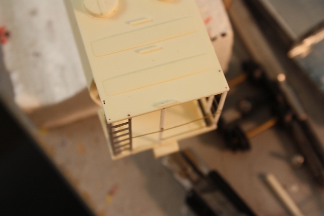
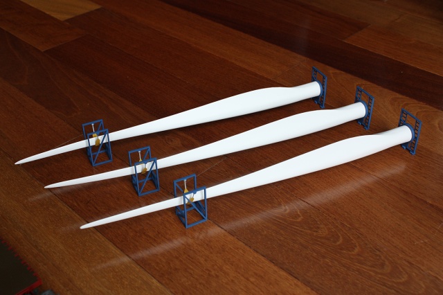
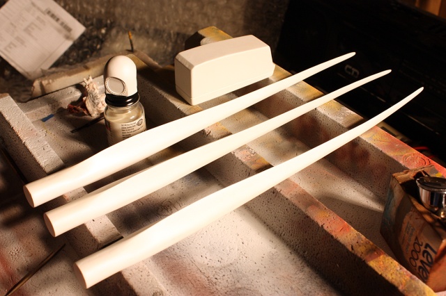
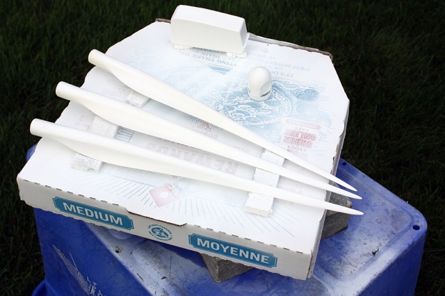
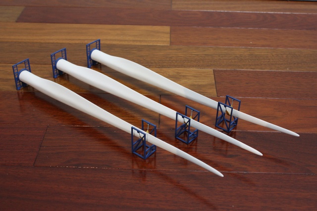
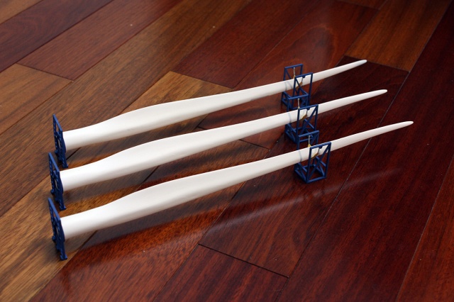
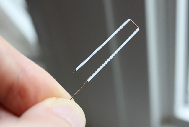
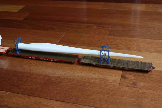
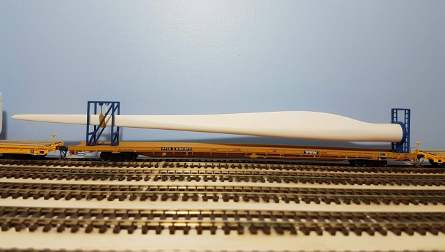
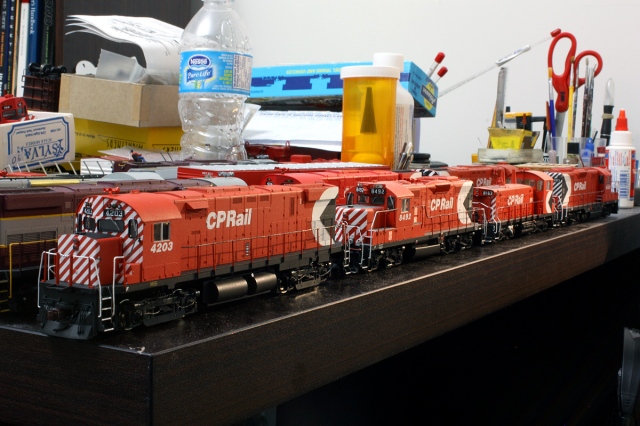
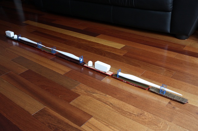
That’s a lot of train, and it’s only 3 blades worth!

26503s-Wind_Turbine_Blades_Flatcars_Batch2.jpg
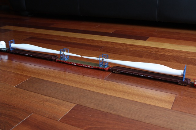
Idler or spacer flatcars are often required to make up for the extra space the wings need. These two wings are on old Walthers 75′ TOFC flatcars, but ideally something like the Atlas 89′ flats should be used. The middle car is a Wheels of Time 60′ CP flat.

26508s-Nacelle_Cone_loads_flatcars.jpg
Cone and nacelle loads on Intermountain and LL P2K flatcar kits. You really only need one set per 3 blades, for obvious reasons.

26501s-Wind_Turbine_Blades_flatcars_Batch2.jpg
Single blade, with a Wheels of Time 60′ CP flatcar and a LL Proto 2000 53’6″ flatcar kit as the idler for the tip support.

And here’s the first batch of wing blade loads on its new owner’s layout, behind a pair of custom CN/Oakway SD60’s that were also painted up in the past:

Wind Turbine Train 4e.jpg
Patched CN SD60’s 5425 & 5479 with a train of wing blades.

Wind Turbine Train 2e.jpg
Mounted on an Atlas 89′ flat, with the tip support on the end of the flatcar instead of on the next flat or idler.


Posted in Uncategorized | Leave a comment

CN 5400-series ex-EMDX / Oakway SD60 Paint-Ups / Patch Jobs

IMG_5066bes-CN-5484-front-left

CN 5484, front left angle. Ain’t she pretty in that blue.

These are always popular with railfans and modelers. CN scooped up a bunch of ex-EMD/Oakway leasing SD60’s (formerly leased to Burlington Northern) a number of years ago. All were renumbered into the 5400 series (previously occupied by now-retired GMD SD50F’s). Many were repainted over time, but initially most were pressed into service in their old colours, but patched with new numbers. They made for a nice change from the standard red and black CN units both trackside and layout-side.

IMG_3715bes-CN-SD60-lineup

Squad in battle formation! CN 5425, 5476 & 5479.

These models started off as Life-Like Proto 2000 SD60’s, released on the market in the early-mid 2000’s or so (Athearn has since also released an SD60). CN 5425 was a complete strip and repaint from an old SOO unit I had (no big loss – the factory painted white & red units sucked), while 5479 started off as a factory-painted Oakway unit that had all the blue masked off and repainted to match the 5425 (they were both going to the same owner). CN 5476 and 5484 were both patch-jobs on factory painted units, with other mods (including adding working ditch lights and LED upgrades) done for others.

It’s not too difficult to patch a factory-painted model – a lot of the paint-up work is already done for you (assuming it’s correct and accurate). For this particular project, you’ll need the numbers from Microscale’s CN HO-scale loco decals (87-567) for the cab and numberboard numbers. I used “CN” letters from a custom set for earlier units (some from a freight car set might work), and CN noodles from the Microscale CN N-scale loco decals (60-567), which are reasonable stand-ins. The paint used to patch was True-Line-Train’s Stencil White, Warm Black, Gloss/Flat Glazes (clear) and VIA Blue, although any blue close enough would probably suffice. Good painter’s tape like Tamiya’s 5mm and 10mm model masking tape is highly recommended, along with all the usual modeling supplies (airbrush, etc).

While I simply painted them up or patched them, in real life most have a good few decades of weathering, and much more ratty and faded blue paint – something to keep in mind if you’re planning a full repaint and considering your blues and weathering options.

This slideshow requires JavaScript.

Fotos? Fotos!

That said, some of the build modifications and details are outlined below:

Cab Details:

  • Twin sunshades over both cab windows.
  • One firecracker style antenna and one shorter cylinder antenna on the roof (placement varied, check photos).
  • Some have an angled beacon support on the front right angled part of the cab (painted white, beacons removed).
  • Rear cab door and wall masked and white stripe extended over (factory painted LL P2K units missed this).
  • Cab numberboards redecaled.
  • Sides of cab patched over blue with airbrush (TLT VIA blue is a decent match), and renumbered with Microscale CN decals (patch jobs varied from unit to unit). Everything clear-coated after, as usual.

Frame/Cab Subbase:

  • Access doors under cab had blue patching applied, and CN lettering or logo applied (early units had “CN” letters applied, later units had a CN noodle logo here. I had some custom “CN” letters I used, and for later units I used CN noodles applied from an Microscale N-scale CN loco set – not entirely accurate as the prototype noodles were much more “squished” than standard, but a decent option).
  • Frame striping applied according to the prototype.
  • Two small round logos applied at each stepwell (the Microscale LLPX decal sheet has similar ones).
  • Holes drilled from inside of pilot ends, and down into the anticlimber above the pilot, to install the stock P2K ditch lights and run magnet wire inside for lighting (some units had ditch lights at both ends, others only the front – CN had retrofitted rear ones on some).
  • Install plow at front only.
  • The stock plastic P2K ditch light castings were drilled out and SMD 0402 LED’s were installed in the housings, with magnet wire running into the anticlimber. I wired each set in series, along with roughly a ~580ohm resistor in the circuit.

Nose (Short Hood) Details:

  • Class lights were patched over, sanded smooth to simulate punch-out plates installed in place (some units like 5425 had the class light and housings fully removed from the nose).
  • EMD logo patched over (how much varied from unit to unit, some just had the logo painted out, some the whole area. There may have been one that kept its front logo).
  • Top of nose masked off and painted black for anti-glare coating (with white sand filler cap)

Long Hood Details:

  • Class lights were patched over, sanded smooth to simulate punch-out plates installed in place.
  • Early patch jobs had all the EMD lettering and logos painted over, later patch jobs that entered service had the lettering left in place, but the EMD logos painted out.
  • Rear numberboards redecalled.

Some Work-In-Progress Shots:

This slideshow requires JavaScript.

Chassis:

  • Milling/cutting/channeling was required to the frame and weight, mostly at the ends, to cut channels to run wiring inside the shell for ditch lights (a lot of work here, as these P2K chassis are packed with weight and were not designed for installing ditch light wiring, or sound for that matter).
  • Truck sideframes either painted or left black, or weathered as desired (on the factory painted units they come silver).
  • The stock lighting system was discarded in favour of 3mm sunny white LEDs, and everything wired to the 8-pin plugs for plugging into decoders.
  • One unit was already equipped with a TCS LL8 DCC decoder. Two units got Digitrax DH165LO’s, while one got a small DH165IP (a tight fit, some additional frame milling may be required – AND be sure to wire the ditch light leads RIGHT TO THE PADS on the IP, as the decoder doesn’t send any power to the spare pin (P3) on the 8-pin plug – ask me how I know).
  • Favourite recommended mod: remove the lousy double-stick tape under the fuel tank, and drill and tap the middle for a 2-56 screw to hold the plastic fuel tank to the chassis. A must-do mod on all the Proto 2000 units I do now.
  • Couplers? No substitute for metal Kadee #58’s, #5’s, or Sergents.

Various Unit Photos and Angles:

A quick gallery of CN 5425, CN 5476 and CN 5479 from a few different angles (they were going to be picked up very soon, so cloudy day photos had to do). And later, CN 5484 was completed for another individual (looks much better on a sunny day, natch):

This slideshow requires JavaScript.

Now, let’s see your 5400…

Posted in Uncategorized | 1 Comment

CP Rail 4203, MLW C424 Build & Paint-up

25650bexs- CP-4203-frontright.jpg
Awww yeeah, action red baby.

Prototype History & Details:

As the 60’s rolled around, Canadian Pacific had fully dieselized its operation throughout the 50’s and retired its last steam locomotives in early-mid 1960. It was swarming with first generation diesel locomotives built for passenger, freight, road and local switching, some new but others getting up there in the ages and coming up for replacement. On top of that, newer, more powerful road freight locomotives were being introduced by manufacturers each year, units that could replace older, worn out, lower horsepower units on a 2-for-3 basis. CP sampled new power in the way of one new Alco-designed “Century” series 2400 horsepower C424 built by the Montreal Locomotive Works in 1963 (8300, later renumbered 4200), and two EMD-designed 2250 horsepower GP30’s from GMD London in the same year (8200-01, later renumbered 5000-01).

Follow-up orders came from GMD for 25 of the upgraded 2500 horsepower GP35 model in 1964-1966 numbered 5002-5025 (originally some were 8200’s), and double that from MLW: 50 more C424’s in 1965-1966 numbered 4201-4250.  The GP30, GP35 and C424 all represented early offerings of the “second generation” of diesel locomotives, i.e., the start of more powerful diesel locomotives that replaced earlier aging first-generation diesels that replaced steam. CP got trade-in credit by trading in some of its older diesels on a 1-to-1 basis (various GP7, FP7, F7B, F9B, FA1/2 and FB1/2, and RS3/RS10). Some of the trade-ins had been in wrecks, others were just older models (some sources may indicate new units were “rebuilt from” trade ins, but that’s simply “paper accounting” and not the case – likely the only things reused were the trucks and some other smaller components).

CP Upgrades(!)

In the 1970’s, CP started making a few modifications to their C424’s. Starting in the mid-70’s, they began replacing the stock MLW door latch handles on the long hood doors with EMD-style “knuckle buster” latches (not done on every single door however). They also started experimenting with different air intake arrangements, replacing the one large intake grill behind the cab with four smaller grills, and later Farr air intake filters in slide-in mounts on the outside of the hood over those openings.

Around 1980, both the GP30/35 and C424 groups were included in CP’s 10-year motive power plan – all were to be rebuilt as roadswitcher DRS-class units, as they had been DRF (Diesel Road Freight) units up until that point for regular road freight service. The 2500hp GP35’s were downgraded to 2250hp for improved reliability out of the 567 engine, which was being pushed to the limit by its GP35 iteration. Sidenote: The GP35’s were also noted by repair staff as being more complex to maintain due to extra transition processes (10 stages in a ’35 vs 4 stages on a GP9, which required electricians to spend extra time calibrating), and many mechanics also loathed the many difficult-to-reach DC brushes in the main generator that could be tricky to change.

Upgrades to both groups included rear numberboards, dual rear head lights and class lights, and a rear pilot. All done to allow them to “properly” lead backwards when operating as single units on branchlines with no turning facilities. The ironic part is that the GP30/35’s were originally built with rear numberboards, but had them removed by CP early on. Horns were also relocated from the cab roof to the rear hood around the exhaust hatch area (position could vary).

Both groups of units continued to serve CP into the 1990’s both in branchline and mainline freight service. The C424’s were based out of St. Luc shops (Montreal QC) for maintenance for most of their lives, and mainly operated in eastern Canada (ON, QC, NB, etc), CP’s lines into Vermont and the north-east USA including the former D&H lines. They did stray to the prairies every so often, and when CP’s GP7/9 fleet was being rebuilt into yard units in the 80’s, a certain motive power planner tended to send C424’s out west to help make up for a shortage of 4-axle roadswitcher power (there are photos of them with GP9’s working prairie grain trains. New GP38-2’s were eventually purchased in the 80’s as prairie power). The GP30/35’s moved around home shops over the years: from St. Luc, Toronto, Winnipeg, to finally out west based out of Alyth (Calgary AB) and Coquitlam BC. The last units of both groups were retired in 1998, but some were converted to 1100-series cab control units and 1120-series cab control road slugs.

Rivet Counting Some Details:

CP 4200 (built as 8300 in the roadswitcher series, later renumbered) was an early “Phase 1” C424 with a number of fuel tank and carbody differences. 4201-4250 that followed were later “Phase 3” C424’s with a rounded rear with no numberboards (initially). CN’s order of C424’s were “Phase 3” with the Phase 2 notched rear end for dual-numberboards (note that the phases aren’t official designations, they’re railfan-invented to describe more significant production changes). In addition, CP 4200, 4201-4209 originally had high-mounted headlights on the cab front, thus the flat area at the top of the cab between the numberboards (relocated to the nose in later years). 4210-4232 came from MLW with low-mounted nose headlights but still retained the (blank) flat area, and 4233-4250 were delivered with low-mounted nose headlights and a regular “knife-edge” cab front with no flat area. Earlier units 4213, 4220 and 4228 got in accidents over time, and ended up getting the later “knife edge” cab faces when rebuilt.

The Model – Starting Point

13905+7bs-QGRY-4212-shell-for-future-CP4203.jpg
Above: Our donor C424 shell to strip down, modify and repaint, sitting on a “loaner” drive chassis borrowed from another model. While it looks ok, it’s been factory lettered for QGRY (do not want!), is in the later 8″ stripe scheme (no multimark, and too modern!), and is a bit lacking in terms of some details (it can haz moar detailed parts?).

This build started off with an Atlas Classic C424 shell factory painted QGRY (one of the Hobbycraft Canada commissioned ones that were released around 2002), which is a somewhat unpopular roadname making them easy project fodder. The Atlas shell tooling is good, but the detailing is on the generic side: while the basic body details are correct, and it has separate handrails and wire grabs, the models suffer from lack of appropriate horns, plows, pilot ends, side bells, truck details – mostly little bits here and there that add up. Some of the front cab detail is a bit iffy as well, mainly the numberboards (they don’t seem square enough to me) and the class lights being positioned offset instead of centered above the numberboards as they should be.

Since the QGRY units are all ex-CP, the same CP shell tooling was used in production by Atlas (Atlas made both original DRF and rebuilt DRS body styles for CP, but in this case they used the later rebuilt style with dual rear headlights/class lights/numberboard). However, our goal was to make an early DRF-class unit with a smooth rear, so all those extra bits had to be removed and filled, and some other modifications to the pilot ends and cab were needed. Happily, the genetic tooling also worked in our favour: Atlas didn’t do any of the later rebuilt air intake filter modifications on their shells (to model this, one can use MbyE parts or intake decals from Highball on styrene bits), nor did they do the replacement “knuckle-buster” door latches (to model this, one can use Archer AR88136 resin door latch decals, or similar etched parts by Plano).

Dig In:

As always, begin by stripping the model down. Atlas typically doesn’t use much glue in these, so the entire decorated model can be disassembled with ease, with most of the grabs easily removed with needle-nose pliers. The main body parts were given a 1-3 hour soaking in 99% isopropyl alcohol, which combined with some old toothbrush scrubbing removes Atlas paint with ease. The painted handrails can also be carefully stripped in alcohol. After a bit of scrubbing to get most of the leftover paint out of the nooks and crannies, it was time to begin modifications.

15713bes-CP-4203-stripped-and-washed.jpg
Above: our bare shell all stripped and washed, with new sand hatch already added (!).

Rear End

13790bs - CP 4210 painted and 4201 unpainted.jpg
Above: A modified C424 shows off its patched buttocks, next to the rear of one that’s already been modified and painted. All the old lights and numberboards were filled in, patched, and sanded smooth. Single rear light reapplied. Also note the rear cut-out lower pilot areas. This photo was from my earlier builds of two in maroon and grey, but the rear modifications are the same for this one.

The rear class lights, numberboard and headlight inserts were removed from the inside, the rear headlights shaved off, and all the holes all filled in with styrene and styrene rod, given Squadron putty to fill any holes, and sanded smooth. Some grab iron hole re-drilling may be required around those parts, and be sure to leave the square sand hatch below them intact. Once everything was dry, a hole was drilled between the two former headlight openings, and one of the removed headlight housings was glued back on to simulate the single headlight mounted at the rear.

The rear pilot had the bottom half between the steps and below halfway up the coupler pocket fully removed, as CP had this area wide open on their DRF road freight units (later filled with a standard rock pilot when the C424’s and GP35’s were rebuilt as DRS units).

Front Pilot

The front pilot end was modified by carving off of the stock mini-V pilot. A new CP “rock pilot” plow was outfitted on the front only (I’ve used both Miniatures by Eric part P18, or the Bowser part 190-582 cut and spliced wider with about 0.040″ of styrene – I used the latter for this built).  For rebuilt DRS units, you’ll need a plow on both ends and ditch lights on the front only. The stock MU lines, cut levers, and some air lines were left off until the end of the build, after painting.

CP-C424-Cal-Scale Pilot Plow mods.jpg
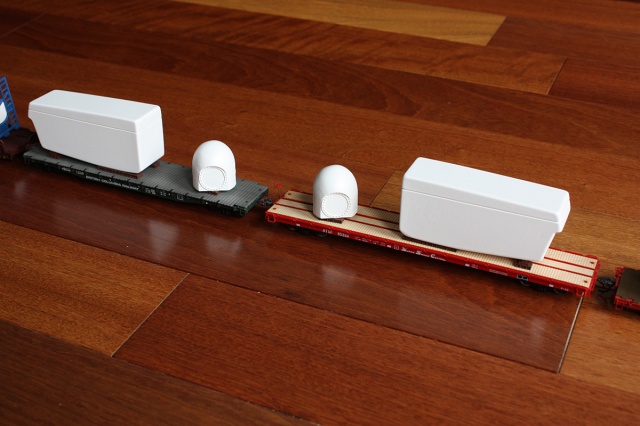
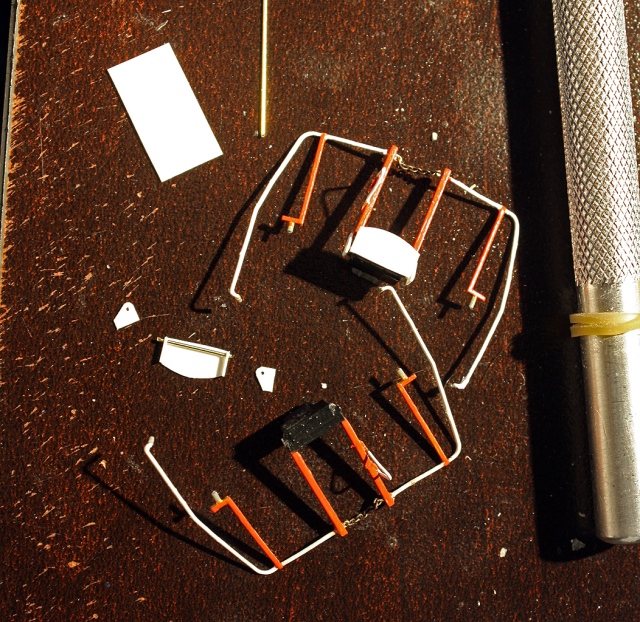
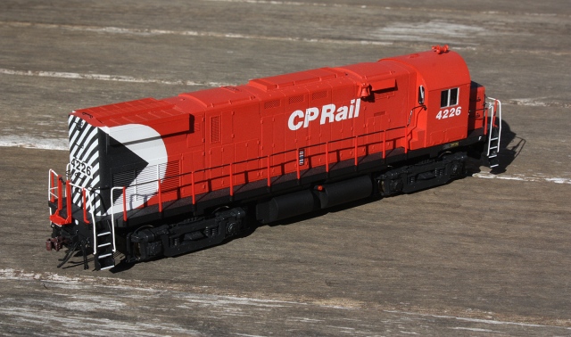
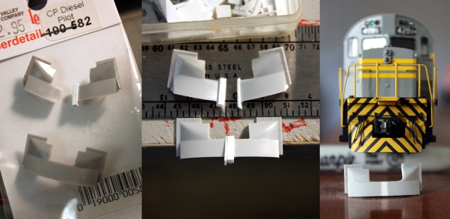
Above: The “rock pilot” plows CP had varied a bit between GMD and MLW offerings, and Bowsers seems closer to the GMD version. We’re using the Bowser plow part, but splicing it with about 0.040″ of styrene to make it the proper width for the C424’s, and also carving a curved notch in one side for the air lines, as seen on the right photo showing a modified, and an already modified and installed/painted plow.

Front Cab and Other Body/Detail Mods

To do a early unit, the top of the front cab face was sanded flat, thin piece of 0.010″ sheet styrene (sanded thinner too) was cut and glued on to match

13700s - CP 4201 cab filing.jpg

24779bes-CP4203-cab-rebuild.jpg
Above: front cab face modifications, with new class light and numberboard gaskets made of wire.

The stock class lights and numberboard housings were also trimmed off (since the numberboards seemed a bit too rounded at the corners, and the class lights were incorrectly offset. New numberboard housings a bit more square were bent from 0.010″ brass wire and glued on. Class light holes were filled, and new ones drilled centered above the front numberboards (the Atlas ones are incorrectly offset to the cab sides for CP units). More 0.010″ wire was bent around a small screwdriver to get the class light gaskets, and they were glued on over the holes.

Holes drilled for windshield wipers above the middles of all front and rear windows. Holes were also drilled on the roof for the Sinclair antenna (Detail Associates part 1802), and the horn (the stock horn hole is in about right). As-delivered CP’s units had M3H’s with the middle bell pointed backwards. Over time many had them re-oriented with the short side bell pointed backward instead, or replaced with newer K3L’s of the same configuration. A Details West AH-268 was used to reflect a unit still equipped with an as-delivered horn, but the Bowser 190-583 M3HR (actually closer to a K3L) and Rapido 102092 diesel horn set (which has some excellent looking M3H’s) are also good options. The stock Atlas cab hole is in about the right place for as-delivered units, but if you’re doing later one, CP relocated the horns to the long hood to reduce cab noise (consult prototype photos for exact unit placement).

Other modifications included:

  • On the side of the cab, the rear cab wind deflector was shaved off each side leaving the front ones.
  • The front and rear cab vents were shortened a touch.
  • The round sand hatch on top of the nose was sliced off and replaced with a square one made from styrene bits.
    A hole was drilled on the right side of the long hood by the engine area, and a Miniatures by Eric B12 side bell was installed.
  • 0.010″ styrene bits were cut and glued to make the sloping “snow shield” intake covers over the front air intakes behind the cab, and installed on both sides on the hood (these were only present on units 4201-4232, and removed when CP modified the air intakes from one large grill into 4 separate smaller intakes in the 1970’s).
  • Wire was bent for the triangular handrail extensions at each end by the drop step, which was mounted into holes drilled in the sides of the end stanchions and painted white/red. As-delivered, CP’s units had a solid handrail and no drop step, but over time units were retrofitted with a drop-step, end chain, and small triangular handrail attached to one of the stanchions.

IMG_8772bexs-EndHandrails.jpg
Above: on the initial 4203 build I used the stock end handrails and drop step that came with the Atlas C424, but on the later 4226 I made some modifications, including replacing the plastic chains at the ends with A-line metal chain (40 links per inch), and scratchbuilt more accurate drop steps and mounts from 0.010″ styrene and thin wire to allow hinging. Also, the angled braces on the two side stanchions were cut off.

IMG_8861bs - CP 4226 drop step.jpg
Above: scratchbuilt working end drop step installed and painted, with extra wire grab iron added on the outside. Also note chain, and triangular handrail extension.

The cab has an interesting story. When I got the shell, the cab sat slightly off on the body, there was some minor damage to the top cab roof overhang at the front, and one of the front window frames was cracked. It was a new “surplus” manufacturer’s shell acquired from a hobby shop (who also had other surplus Atlas RS3 and C424 shells for sale), but I suspect this particular shell took a tumble to the floor at some point in its life, resulting in the damage. The window frame crack was repaired by carefully drilling two holes in the window frame and inserting a piece of steel wire and glue to splice the cracked area together. The cab sat properly when re-adjusted on the body. And, since I had originally earmarked this unit to become a later 4200 with the “knife-edge cab” front, I made repairs to the top cab roof overhang.

I originally got as far as painting the body with a few coats of grey, painting up all the handrails maroon/yellow, and detailing/painting the frame/walkways black before setting it aside (it was going to become a later 4200 in maroon and grey, the third after doing 4210 and 4201 just prior). I got sidetracked with other projects and the shell sat in the projects box for a few years, before the urge to do an action red unit came up. Ideally I wanted to do one of the early 4200’s with a flat front again since Atlas never made that version in CP, and it had to be an earlier 5″ stripe unit. So this shell was reluctantly pulled out, the area of the cab roof that had been fixed was filed flat, and the handrails repainted red and black.

24625.JPG
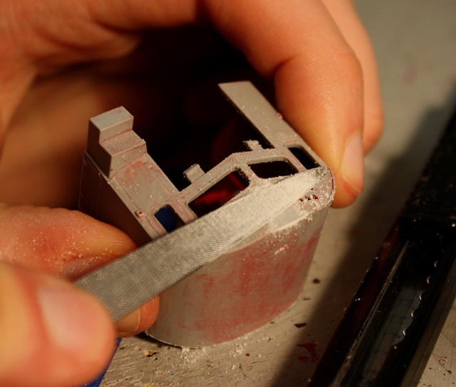
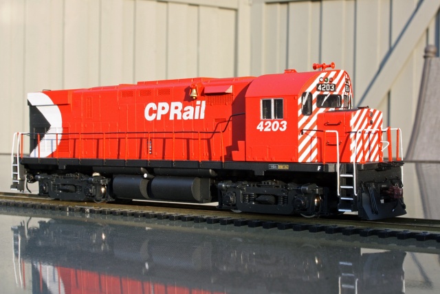
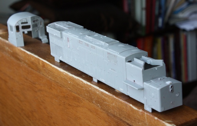
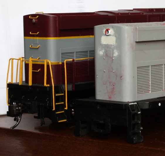
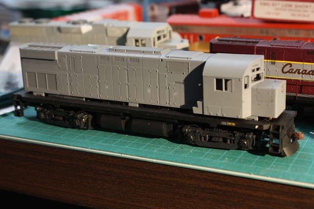
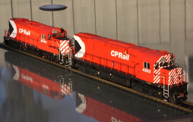
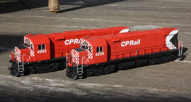
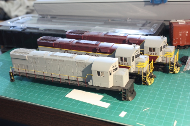
Above: The future CP 4203 sits uncertain of what colours she will wear, next to completed CP 4201 & 4210 in maroon & grey – two other former QGRY shells given a complete makeover.

Chassis

The current Atlas Classic chassis is a fine, smooth running choice, and if your unit comes with it you should use it. However as ours was just acquired as a shell, it needed a drive. You’re in luck: older Atlas “Yellow box” C424/C425’s built by Kato in Japan have just a smooth a drive, are in easy and cheap supply, and fit the newer Atlas shells (The older models are informally known as “Atlas Japan”, “Atlas Yellow Box”  or “Atlas Kato” units, versus “Atlas China” or “Atlas Classic” for more recent production runs).

The only real modification required to the older Atlas-Kato drive, since those older shells had body-mounted couplers, is to either body mount them on the newer shell, or build a coupler mount extension on the chassis, which is what we elected to do.

IMG_5797bes-Atlas-C424-frame-mods.jpg
Above: drilling holes in the frame and pieces of brass to make chassis-mounted coupler mounts on the older Atlas-Kato C424/C425 chassis.

Thick brass 0.040″ strip was cut to size into two extensions, and holes were drilled in each for mounting to the chassis. Two holes were then drilled into the chassis ends, and everything was tapped for 2-56 screws. The ends were then fastened with short 2-56 3/16screws , and once everything was lined up and fit snug, coupler pockets were test-fit and another hole was drilled in each brass mount and tapped for a 2-56 screw.

IMG_5799es-AtlasC424FrameMods.jpg
Above: Holes drilled in the frame and brass extensions. The holes in the extensions were drilled a little bit larger to enable minor adjustment.

25316bes-Atlas-Kato-Alco-C424-chassis.jpg
Above: once tapped for 2-56 screws, the extensions were added and screwed to the frame using short 2-56 screws.

A small styrene mount was then required to be build up at the ends, to get the correct coupler box height.

IMG_5804es-CP-4226-C424- coupler-mount.jpg
Above: In addition to the 0.040″ brass extensions, a small styrene mount about 0.060″ thick was made to get the Kadee coupler boxes to the correct height. Some extra styrene bits were added to act as a “stop” when the coupler boxes are inserted.

25710bes-Atlas-Kato_C424_Chassis_modified.jpg
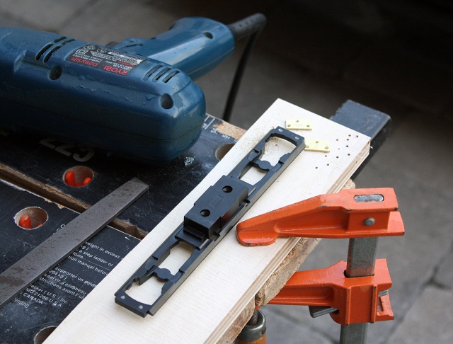
Above: the modified Atlas-Kato chassis, with end coupler extensions added and some new lighting. Rebuilt fuel tank also added (see next section).

Another modification I made was to the weights, which are hefty, but just sit loose inside the Atlas-Kato shell. I filed the inside tips down a bit so they were level with the stock plastic grey conduct on top of the motor, drilled and tapped, and fastened the weights on with thick styrene bits.

25711bes-Atlas-Kato-WeightScrews.jpg

At this point one can make any wiring  changes, add a decoder, better lighting, etc. I added a pair of 3mm sunny white LEDs and 680ohm resistors to each end, just hardwired to the stock lighting system for now. They’re suspended at each end from wire CA glued to the ends of the weight at headlight level. Notches were cut under the front weight to allow room to run the headlights so they didn’t interfere with the gear tower.

Fuel Tank

Since I acquired an Atlas/Kato C425 drive for my CP C424 project, it came with the solid one-piece fuel tank, but needed the proper split fuel tank. There’s a guy on eBay that sells Atlas parts who usually has that sort of thing, but unfortunately no bueno.

No matter, the snap-on one-piece tank sections on the Atlas C425 tank are easily removed for modification. The air tanks were carefully trimmed off the tops (to be mounted to the chassis later), and the fuel tanks were then cut in half. The open ends were filled with styrene and Squadron putty, sanded smooth, and the sliced tank halves glued back on in the proper orientation. Some styrene was used to lengthen the ends and add other bits such as fuel filler detail. Once painted black, it’ll all look nice and clean under the unit.

25336bes-FuelTank-C425toC424.jpg
Above: The old fuel tank bits sliced up and re-assembled, awaiting a coat of black paint.

Trucks Sideframes

Most of CP’s MLW locomotives delivered during this era had SKF roller bearings, and small axle generators for the wheel-slip system on each axle on one side. The stock Atlas slideframes have the old stock slope bearing caps, that some CP C424 units got from older power when axles were swapped around. So, we’re going to re-equip this unit properly.

One nice bonus with the Bowser C630M’s is they came with a full set of axle generators to add to their trucks as per the prototype. Those, and the SKF bearing caps the sideframes came with stock, can be shaved or sanded thin and added to Atlas sideframes (after the Atlas end caps are shaved off) to give the proper SKF or axle generator bearings for CP C424’s, RS3’s, FA’s, etc. Some thin wire or string can be used for the axle generator cables. All the left (conductor’s) side axles are axle generators on CP units, while all the right (engineer’s) side are SKF end cap bearings. Note, some units later got a speed recorder on the #2 axle on the engineer’s side.

Also, one needs to add the brake rigging chain setup at the front left side. The truck sideframes are slippery plastic, but can be drilled for wires.

IMG_8782bes - Scratchbuilding Brake Chain.jpg
Above: Scratchbuilt brake chain and rigging, done with A-line chain. Some thin bits of 0.010″ and 0.020″ styrene cut to the appropriate pulley shape, and a nut-bolt-washer (NBW) bit from Detail Associates was used to retain the chain in the pulley. Some spare bits of styrene sprue were used as the chain guide (a small bit of wire bent into an eyebolt connects the chain to it), with metal wire mounts that run to the frame.

IMG_8860es - CP 4226 brake chain.jpg
Above: completed brake chain rigging added to the front left truck sideframe. Holes were drilled in the brake cylinder rigging on the truck sideframe, and the pulley and chain were fastened to it via bits of wire. I did this on the 4226 build, and retrofitted 4203 with it at the same time.

Paint & Decals

After priming the body with grey paint, it was then given a few coats of TLT CP Action Red (since discontinued, but Tru-Colour Paint’s TCP-024 is  a very good match), and then a coat of TLT Gloss Glaze clear. The underframe, cast in black plastic, was given a few coats of TLT Warm Black followed by a coat of clear as well.

IMG_6874s.jpg
Above: After modifications were complete, the body of the unit was given a coat of primer grey. At this point, the underframe had already been painted black, clear, and decalling had begun (this one is the 4226 build).

24890bs-CP-4203-painted.jpg
Above: after the grey was dry, a few coats of action red were applied, clearcoated, and the unit was ready for its rear multimark and lettering/numbering (this one is the 4203 build).

The multimark was then masked and sprayed on according to my handy-dandy how-to writeup. The C424’s are probably the worst units to try applying multimark decals to (and I know – I’ve wasted a lot of Microsol trying to work the decals into and around the deep rear grills on other units) so for this application it’s a real time saver and looks great. Just take a gander at 4203’s rump end:

27064bes - CP 4226 multimarks paint shop.jpg
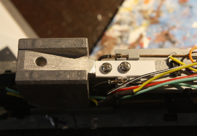
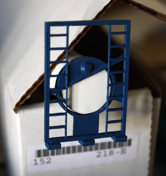
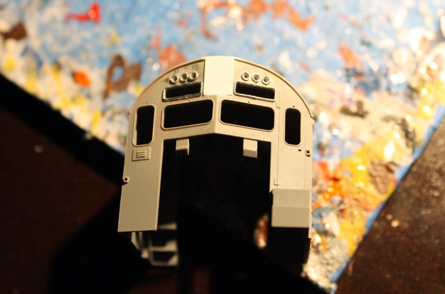
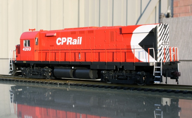
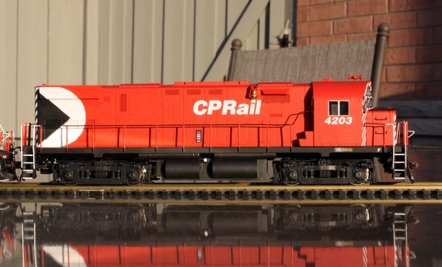
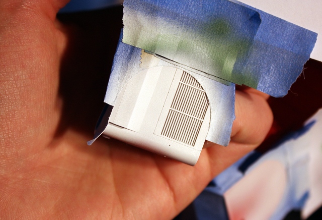
Above: spraying on the initial white after masking the round section. Unlike using decals, there’s no hassle getting it into the deep grill area at the back!

24967es-CP4203-multimark-logo.jpg
Above: no decals, no Microsol, no poking, no prodding, no fuss, no muss. A painted on C424 multimark is its own reward.

TLT warm black was used for the underframe and fuel tank, as well as the black parts of the multimark and rear end area, and TLT stencil white for the white areas of the multimark. The handrails were painted similarly (be sure to paint the bits of the handrail stanchions below the underframe black, a lot of people miss this detail). The step faces were carefully painted white, along with the fuel filler (varied, could be white or red). The bell was given a mix of gold-silver to make it appear as a shiny brass bell like some units had.

The decals were from the usual Microscale CP lettering and 5″ stripe sets. The front stripes took a few tries to get lined up correctly, as due to tooling and printing differences they don’t always exactly line up like the prototype. Working them around some of the numberboard/class light/window details on the front cab face was a challenge, and some had to be applied in bits and pieces, and touched up with paint. All the cab window, numberboard and class light gaskets were then hand painted black. The rear number was originally black numbering on a white background, but eventually changed to white numbers on a black background. No frame dots for the mid-70’s era units.

25427bs-CP-4203-shop-track.jpg
Above: CP 4203 on the “shop track” getting decalled. Handrails still need to be repainted, as does the fuel tank, and a lot of other bits need to be added.

Above: cab and end decalling progresses. The numberboards were later filled in with styrene bits, painted black, and decalled.

Additionally, some class decals came from a Black Cat CP maroon & grey unit set (sometimes units retained their yellow-outlined class plates, instead of having them repainted). The front numberboard cab decals in the Microscale set are a bit too large for CP’s C424’s, so the slightly smaller ones with the Black Cat set were used (and look great). The builder’s plate on the right side under the cab is a modified Microscale one to act as a stand-in for an MLW builder’s plate (I’m not aware anyone makes a correct one).

The fine plastic wipers were painted silver and glued in the holes drilled earlier in the cab. They came from an Atlas GP38/40 wiper set, and were close to what the C424’s had.

Glamour Shots:

25649es-CP-4203-side.jpg
Above: CP 4203 front-left view. Note all axle generator cables installed.

25654bs-CP4203-rearleft.jpg
Above: CP 4203 rear left shot. Note the open rear pilot area.

25655bs-CP-4203-rearright.jpg
Above: CP 4203 rear right shot. The sun was setting and low at the time, hence the unintended shadow of the photographer.

25656s-CP 4203 C424 & 8492 GP9.jpg
Above: CP GP9 8492, a custom chop-nose GP9, also came out to play in the sun.

25657bes-CP-4203-rightside.jpg
Above: CP 4203, right side view.

25641exs.jpg
Above: messy shop desk parade: CP 4203, 8492, 8163 & 8485.

Addendum: CP 4226

A few months after completion of 4203, a second unit was started using the same methods (and some improvements noted above), done up as sister unit 4226.

IMG_9317bs-CP-4226-MLW-C424.jpg
Above: CP 4226 front left view, note the brake chain rigging and more accurate drop steps were added to this build.

IMG_9320bs-CP-4226-MLW-C424.jpg
Above: CP 4226 rear right view. Pre-roadswitcher end pilot cutout featured on the rear, as well as blank rear end with single top headlight. Note rear number, earlier repaints had black numbers on a white rectangular background, but that changed later on to white numbers on a black background.

IMG_9318bs-CP-4226-MLW-C424.jpg
Above: CP 4226 front right view. Also note, the red (steel) bell on this unit, as opposed to the brass one on 4203.

IMG_9322bs-CP-4226-MLW-C424.jpg
Above: CP 4226 rear left. After rebuilding as roadswitchers in the 1980’s, that as-delivered front horn would be relocated to near the rear exhaust hatch area (position could vary).

IMG_9328bs-CP-4226-4203-MLW-C424-duo.jpg
Above: CP 4226 and 4203 side-by-side. One can notice a very slight difference in shade between both units (even though the same TLT CP Action Red paint was used on both), caused by using a gloss finish on 4203 (TLT Gloss Glaze clear) and a semi-gloss finish on 4226 (Model Master Semi-Gloss clear). This is only really noticeable in bright light conditions such as this, and paint did vary on the prototype depending on how fresh or how old a unit’s paint job was.

Posted in Uncategorized | 5 Comments

CN 567417 – the High Class Roller of 40′ Boxcars

IMG_5421s - CN 567417 boxcar yellow door.jpg
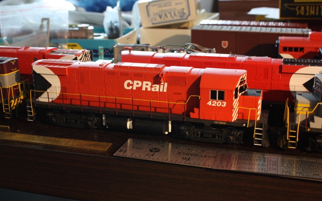
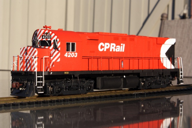
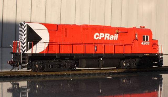
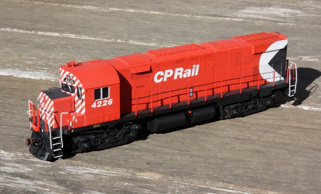
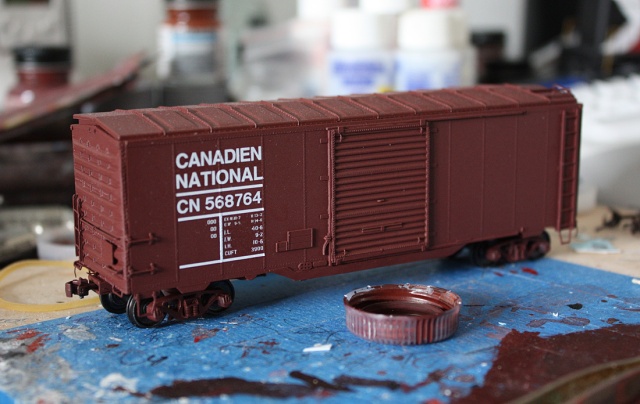
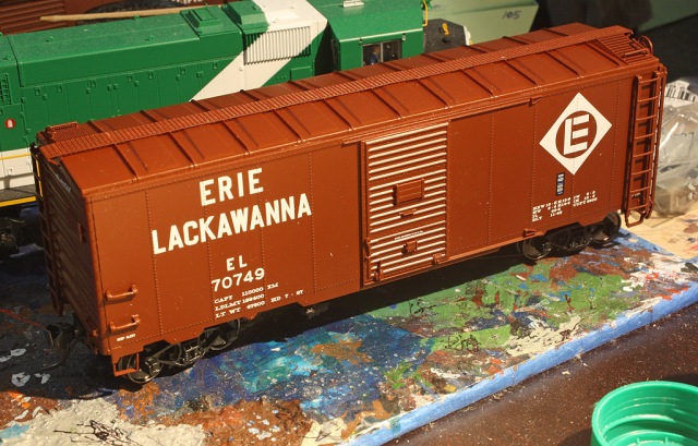
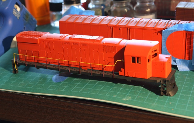
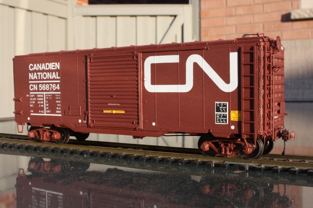
Above: Freshly shopped and ready for hauling some newsprint rolls.

The fun part about building boxcars is you can have endless variety to play with: a boring 40′ boxcar might look like the next boring 40′ boxcar, and it probably is to most people, but there’s often little details, intricacies and changes between any two specimens picked out of a sample population. And why have one, when you can have…two? *Raises eyebrow*.

This particular specimen, CN 567417, was another one of the “Bramalea Trifecta” that sat on a disused spur at Consumers Glass (later Owens Illinois) in Brampton, until they went bye-bye a few years back (all cut up for scrap). It was one of many old outdated 6′ door 40′ boxcars CN rebuilt in the 60’s and 70’s with larger 9′ doors to allow easier forklift loading. Historically, they had scads and scads of the things, so why not put them to good use continuing to make money.

CGXX CN 567417 40' boxcar behind Owens Illinois in Brampton.jpg
Above: Looking closely at the prototype car,  you can seen that the door is in fact, yellow. Faded yellow, or painted over yellow, but yellow – more on why later. Another thing to keep in mind is the brown paint’s had at least two decades if not more of sun tanning sans SPF 100 and umbrella, so has shifted from a darker brown to a faded red. Someone need to tell the Ontario Ministry of Transportation to do a better job trimming their bushes, as that inconveniently placed one hides a better view of the door.

Always research and know your prototype: my intel gathered through various sources say this little 40’er (for the detail inclined: 10’6″ roof, AAR 1944 variety, so you don’t buy the wrong kit to build) was originally built by the Eastern Car Company as CN 534856 in October of 1952, and rebuilt by CN in March 1971 with 9′ doors. Disposition is the same as 568764 – retired, sold to Consumers Glass in Brampton Ont. as a storage shed, sat around for years in view of everyone passing by on Highway 410, and finally cut up to become new soup cans and Toyotas in July 2014. Such is the fate of many old freight cars.

Quickie Build Notes / You’ve Seen This Before.

The model started off as a Branchline Blueprint HO-scale kit, and was built basically the same way the CN 568764 build article outlines (it’s a great article, I recommend clicking it after reading this page). Notably the door, door track, and sill modifications were done the same way.

24323s - CN 567417 start.jpg
Above: Even with the new 9′ door on, it doesn’t look like much. But, that’s how most things in life start out. The difference is if they still look like that in 2 years after putting it in the box in frustration or not (this one only took 7 months). The very shiny Amtrak Superliner in the background was one of many in for client contract work. The whole desk was literally full of them, and the shine was blinding anyone passing by.

But the spice of life is change, and a few changes were made to reflect the prototype more accurately: a newer diagonal panel roof was added (in place of the kit’s stock raised-panel roof), the original Improved Dreadnaught Ends in the kit were kept (with the top pins trimmed narrower). As well, the sill tabs for the stirrup steps were trimmed off, as this was rebuilt from a later car that had stirrups mounted to the underside of the body and to the ladders (this often varied depending on the car rebuilt, and sometimes CN messed around with this). Tichy 8-rug ladders with the stirrups attached were used in place of the stock kit’s ladders, and bent wire rugs for the “left” side stirrups. The usual amount of grab irons, underbody details, and other tiny knick-knacks that shoot out of tweezers and get lost on the floor were then added (on the plus side, every time you clean your desk or floor, you find some new parts).

24776s - CN 567417 detailed.jpg
Above: In best Dom DeLuise voice: “Awesome, Wonderful!” CN 567417 is nearly done up to the nines with the usual fancy detailing, and nearly ready for a night on the town the basement paint shoppe queue.

Paint, paint, paint!…this car was painted in its as-rebuilt early 70’s appearance, complete with flashy yellow door CN applied to designate for handling paper, newsprint, and other high-class merchandise (as these cars got older and newer, younger and better looking 50 foot boxes replaced them, the doors were often repainted or painted brown for general merchandise use). Early COTS single-block stencils and ACI car tags were also applied for that 70’s style.

The brown body paint was custom mixed (twice – funny story: I ran out of my custom mix when I painted 567417 and 440601, so didn’t have any for 568764. Hours were spent playing with different paint-matching mixes to get one mixed close, very close, oh so close, to the other two. It’s so close that 99.99/100 people can’t pick out the difference, but of course I can). The decals were the custom set by Sean Steele/Canuck Models (I won an extra freebie set by guessing the tiny lettering that was too small to read, in fact, said it was too small to read). The yellow doors were painted with a mix of TLT CP Diesel Yellow and CP Action Yellow to give a freshly shopped look. So delish.

The usual amount bling-bling was added: coupler boxes drilled and tapped for 2-56 screws, Kadee #58 couplers all around, the stock Branchline metal wheelsets and truck frames (painted brown, because that’s how CN rolled). Enfin, achevée!

Glamour shots:

IMG_5422bs - CN 567417 boxcar yellow door.jpg
Above: B-end, with top view. That yellow lettering box, applied only by the tall B-end ladders, warns people that they’re in for a surprise if they think that ladder leads to a roofwalk.

Again, as I mentioned in the last article, that french lettering often isn’t on the side you think it’s on, so always check and double-check your reference photos.

IMG_5423s - CN 567417 boxcar yellow door.jpg
Above: Angled A-end ground view. Around what you’d probably see if you too were 1:87 scale.

IMG_5424s - CN 567417 & 568764 boxcar ends.jpg
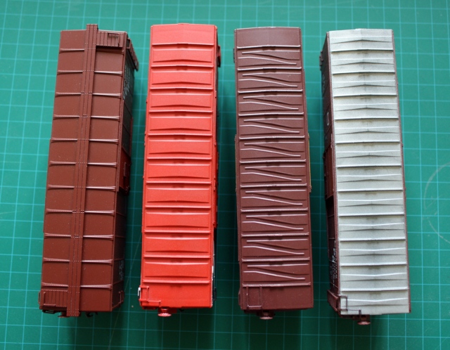
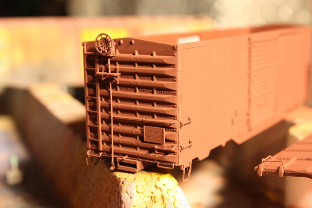
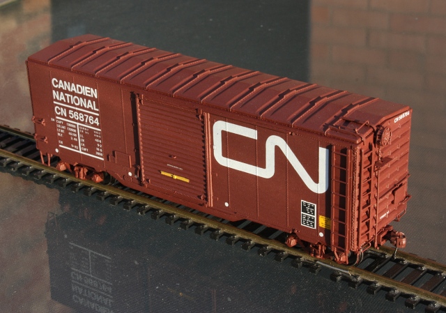
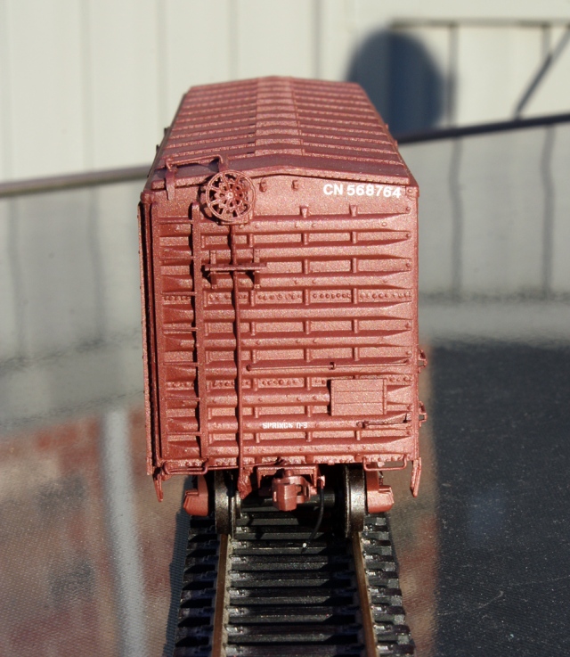
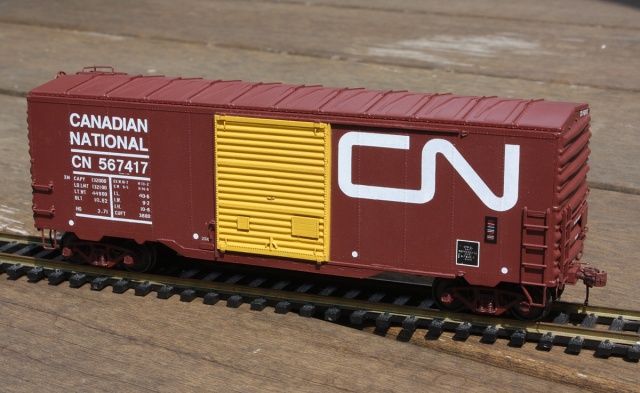
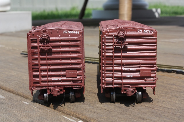
Above: Comparing the ribbed NSC-2 ends on 568764 to the Improved Dreadnaught (IDE) ends on 567417. Even as I type this, I have to remind myself to go back and fix that loose brakewheel grating walkway on 567417. _Someone_keeps_forgetting_.

IMG_5425bs - CN 567417 boxcar yellow door.jpg
Above: Bros chillin’ on the patio with brewskies: two “XM”s (AAR code for general boxcar) mingle together, awaiting a call to duty.

More boxcar madness to follow? Perhaps, perhaps not…

Posted in Uncategorized | 1 Comment

Eye-Spy: CN Weston Sub – Highbury Industrial Lead, Rexdale Part 2

It’s been a while since I’ve done one of these. I’d like to do more (and have a list of ideas), but time and other priorities pop up.

Our first installment way back, Part 1, dealt with some of the customers located at the east end of Rexdale around Islington/Highway 401. Now we’ll look at a long, winding spur known as CN’s Highbury Industrial Lead, and many of the past (and present) local industries along it that utilized rail to ship their goods.

History

Located in Rexdale at Mile 11.7 of CN’s Weston Sub (the line running between Brampton and Toronto, formerly the Brampton Sub until the mid 60’s, and presently owned by Metrolinx/GO Transit since February 2009), the long winding track was built in the mid-50’s to serve the hive of industry popping up in the new Rexdale area of Etobicoke, that in the post-war period was being developed from sprawling farmland into sprawling neighbourhoods and factories.

The area pre-development in 1950, and shown progressing in 1956. This and further aerial closeups below are from the City of Toronto Archives imagery from various years between 1950-1985 as-noted (source, and a very handy one at that).

CN’s employee timetables for that era show the new spur line designated as the Highbury Industrial Lead, as it’s still known today in present timetables. Car Control diagrams for the 60’s include it as part of the Rexdale Industrial Zone, Zone X (i.e. each of the sidings here have X-prefixes. E.g. X-211, X-226, etc):

CN Highbury Industrial Lead aerial Rexdale 2 (1969) D copyX.jpg
Above: CN’s Highbury Industrial Lead, highlighted in green, winding its way through the Rexdale section of Etobicoke in 1969, along the Highway 27 corridor, with major roads and customers listed. Additional spurs and sidings (blue) off the mainline (yellow) will be covered in a future installment as time permits For a larger zoom-able image, click here.

There’s plenty of early aerial imagery of the area, here’s the trackage in 1960 as development further progressed:

Tour of the Line, and Industries

From research over time on the various local industries, access to a few select CN employee timetables dating from the 1960’s-80’s, as well as a handy Car Control diagram booklet or two, I’ve been able to piece together some of the local customers that used rail back in the day, and those that still do:

Starting at the top:Rexdale 2 (1969) G+ copy.jpg
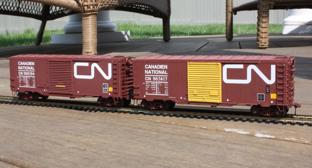
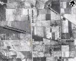
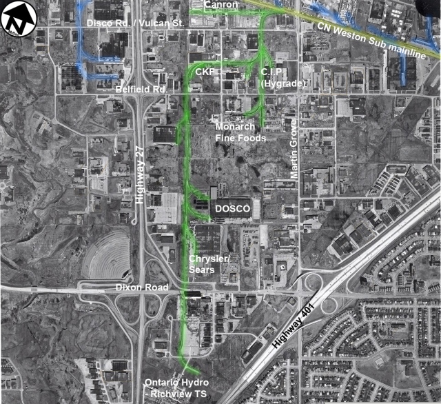
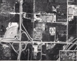
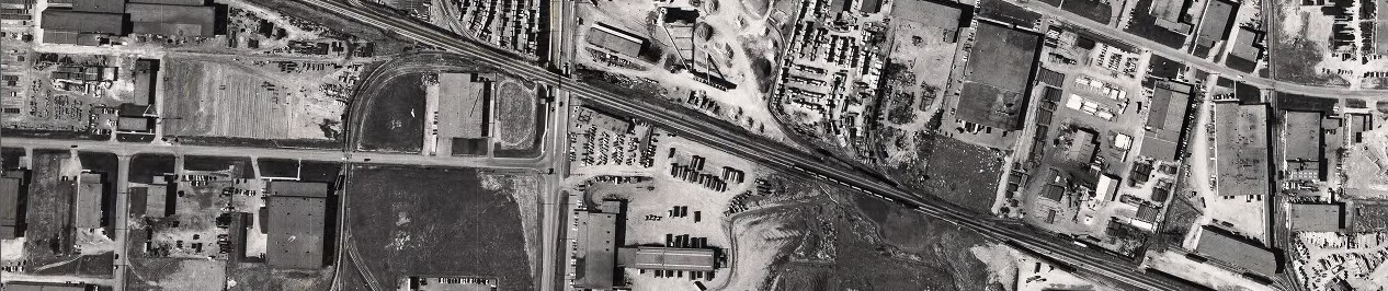
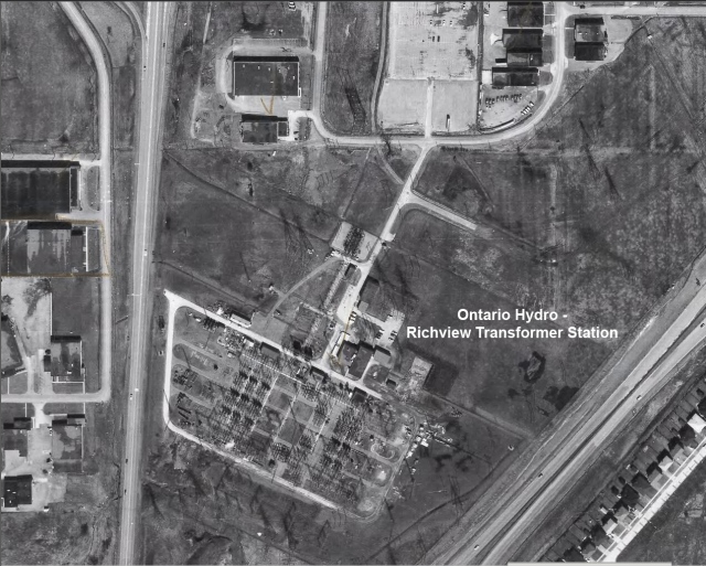
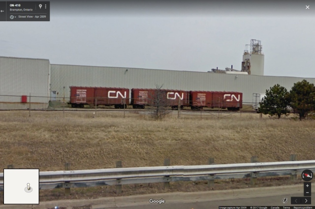
Above: Customers in the area between the CN Weston Sub and north of Belfield Rd c.1969. Check out that string of 40′ boxcars just sitting there. Gone today, but everywhere back then.

Canadian Iron & Foundy (Canron) – Pressure Pipe Divison

A large iron and steel structural fabricator, they were responsible for much of the construction of the CN Tower, as well as many other large building and structural projects in Canada. As with most large national firms back in the day, they had diverse interests and complementary holdings. Located here in the 1950’s was their Pressure Pipe Division site (their structural division site was located west of Highway 27 on another spur), a large sprawling property with lots of metal and pipe stacked up (potential flatcar and gondola loads, note the line of empty bulkhead flatcars).

Canron originally entered the plastic pipe business by acquiring Grandview Industries and Johns-Manville Pipe, and over time they focused solely on plastic pipe manufacturing. Canron’s pipe division was later acquired by Ivaco Inc (Montreal QC), who owned it until the 1992 merger between Scepter Manufacturing (maker of those red plastic jerry gas cans) and Canron Pipe (forming IPEX, which still has a site west of Highway 27 that gets occasional rail service).

It’s unknown when they left this site, but 1985 aerial imagery shows the property cleared and the building undergoing partial demolition. By 1987 some additional new buildings were being built on site (it appears the rail spur may have been removed then), and today a trucking/ transportation warehouse occupies the property. Note that Canron continued to use their other property west of Highway 27 until around 2004, but more on that in another post.

Status: past customer. Site redeveloped, no rail.

Canadian Keyes Fibre Company Limited (CKF Inc.)

A Canadian manufacturer of food and retail packaging, disposable plates and utensils from a variety of different materials, CKF has been operating at this site since the 50’s. Eventually their small square building expanded and presently occupies the entire block. Rail traffic: covered hoppers of raw material used in the manufacture of their products.

Status: current active rail customer.

Highbury Developments Ltd

I haven’t been able to find too much information on Highbury Developments Ltd. The only reference I can find is an old Supreme Court of Canada case between the Etobicoke Board of Education and Highbury Developments Ltd. over a land dispute. What can be gleamed from that amid all the legalese is Highbury was a land developer in the 1950’s who owned parcels of land in Etobicoke it was developing for residential and presumably industrial use. Perhaps they developed some of this industrial area of Etobicoke (hence the name of the industrial lead/spur), although it could have just been named such because they were an early customer along it. This is the perfect example of old names living on on the railway decades after the original companies or people vanish, and nobody really knowing why they’re called that name anymore.

Extra digging didn’t yield further useful information about the company beyond that – perhaps they were bought out or went under sometime in the 60’s. The main building appeared under construction in 1958 aerial imagery and in 1960 appears to have construction equipment including cranes in their lot, in addition to a rail siding.

By (or sometime before) 1969, the property was occupied by Westeel Rosco Ltd., who had a number of sites in the Rexdale area back in the day. Originally Rosco Metal Products Limited, Westeel (Western Steel Products Limited) acquired them in 1965, hence the name. They were an industrial and agricultural  metal company, dealing with sheet metal, siding, roofing products, and agricultural storage bins (source).

Eventually
this site was cleared and built over by CKF’s ever-expanding factory, circa 1987.

Status: past customer (property developed over)

Air Reduction Company Ltd.

Otherwise known as “AIRCO”: a New York based supplier of  industrial gases (oxygen, argon, etc) for welding and other uses. Given the size of the building, it was probably a local distribution centre.

Status: past customer or vacated, no rail.

Sylvania Electric

Large light bulb and electronics manufacturer. Again, judging by the size of the building it was likely another local distribution centre or warehouse, which were often located in industrial areas in the suburbs where land was cheap and with nearby access to highways and rail lines. The building is currently home to Brenntag Canada (chemical distributor), who gets rail service (tanks).

Status: active customer (Brenntag).

C.I.P. Ltd. (Hygrade Corrugated Containers)

Formerly the Continental Wood Products Company, they changed their name in 1966 to Hygrade Corrugated Containers Ltd. Again, likely another container and packaging manufacturer.

The site has changed hands in the past and is currently occupied by big box building supply store Rona, who gets inbound lumber loads on centre-beam flatcars. Here is a photo of a CN local servicing Rona, taken by “Cityslicker” via Railpictures.ca:  http://www.railpictures.ca/?attachment_id=17619

Status: active customer (Rona).

Ambassador Books

Not entirely sure what the deal here was, but it appears Ambassador Books was a Toronto-based book and print publisher back in the day. It was the 60’s after all – small companies having their own private rail sidings and spurs was much more common then than now. Being a publisher, boxcars of newsprint rolls and inbound/outbound loads of printed products would have been the likely traffic, if this site was a printing operation and not just a distribution warehouse.

Status: past customer or vacated, no rail.

Moving south to Belfield Road:Rexdale 2 (1969) H+3v copy.jpg
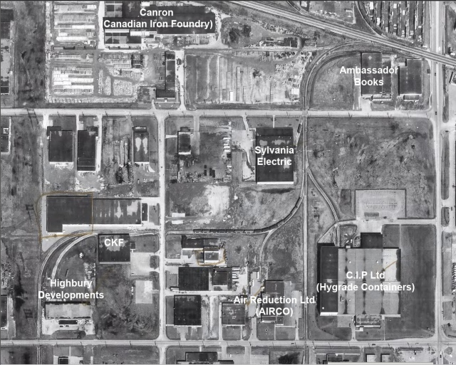
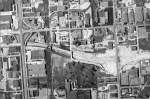
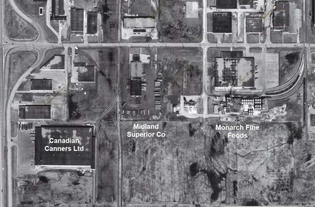
Above: Customers in the area below Belfield Rd., c.1969. The line headed south along the Ontario Hydro corridor, and serviced customers on either side. Highway 27 and the local service road (City View Dr.) can be seen at the far left.

Monarch Fine Foods

Opened at 195 Belfield Rd. as Monarch Fine Foods in the early 1960’s, the plant later became Thomas J. Lipton Inc (T.J. Lipton of soup making fame. Both Monarch and T.J.Lipton brands merged in 1993 under the Lipton banner), before becoming Unilever in the 2000’s (Unilever always had a corporate stake in Lipton). The plant makes Becel brand margarine and Hellmann’s brand mayonnaise (source), and takes in tank cars on its three tracks. In the past it has handled reefers as well, probably for outbound product, but most of that kind of rail traffic now travels in refrigerated trucks and containers today.

Status: current customer (Unilever)

Midland Superior Co.

Midland Superior Co. was a trucking company, this is likely one of their road-rail transload terminal/warehouse operations. Apparently the company was CN owned, they were eventually merged into a CN trucking firm, which was later spun off.

Status: past customer or vacated, no rail.

Canadian Canners Ltd (as Aylmer Foods Warehousing Ltd)

Built in 1962 as part of a joint venture between Canadian Canners Ltd and Three Highways Warehouse Ltd (forming joint venture Aylmer Foods Warehousing Ltd), a 120,000 square foot warehouse was built at 55 City View Dr. Rexdale to facilitate product distribution in Ontario and to the east. The operation was discontinued and warehouse sold off in 1981.

Canadian Canners Ltd. (and their Alymer brand) dealt with canning various perishable food items such as canned fruits, sauces, and tomatoes, peaches, pears, Del Monte juice drinks, done in various factories in southern Ontario and Canada. On the King’s Highway 409 page, you can see CN 50′ insulated boxcars on the spur, par for the course for carrying canned food perishables by rail at the time (due to the tight curve, it’s noted in timetable that cars greater than 50′ were prohibited on this siding).

In recent years Thomson Terminals Ltd (trucking/transport/logistics) has been the longtime tenant of the building and was a user of rail service. More on them in a bit.

As for Canadian Canners, Del Monte of California had control over the company for a while, but it was eventually absorbed into Nabisco in the mid-80’s.

(Source: The History of Canadian Canners Ltd)

Status: past customer, no rail service.

Highway 409 Hits The Scene.

When Highway 409 was constructed through this area of Etobicoke in the mid-1970’s, the highway was built below-grade and squeezed around much of the existing development. Bridges were built at-grade over the highway  for the main rail spur and customer sidings, as well as Hwy 27, local and access roads. Some excellent 1978 photos of the completed area can be seen in the Highway 409 photos section of the King’s Highway Page. Note the GMD switchers, standard fare switching power for the time on CN.

Above: Highway 409 construction progression in 1973 vs 1975.

Rexdale aerial Hwy 409 1985.jpg
The above shows a 1985 aerial view of where Highway 409 now runs, showing the various bridges needed for the main spur and sidings. Canadian Canners Ltd. on the left eventually became a Thomson Terminals Ltd warehouse. Below, another warehouse on the lower left built in the 70’s (unknown who used it at the time but Thomson Terminals also owns it today) received rail service via two curved sidings leading in between the buildings. The only hint of that today is a nick at the corner of one of the buildings to allow the tight curvature. And yet another warehouse was built in the early 80’s opposite the Canadian Canners site, on the east side of the tracks (off Iron Rd) with its own siding as shown above (yes, also currently also home to Thomson Terminals). Original and previous ownership is often difficult to ascertain in cases like this, as tenants changed over time, and old Car Control diagrams and track maps only show a limited snapshot of what or who was there at the time.

Continuing south below Highway 409:Rexdale 2 (1969) F copy.jpg
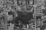
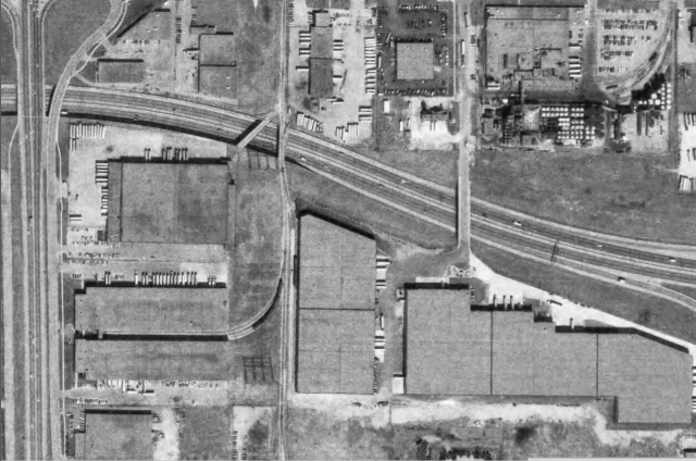
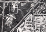
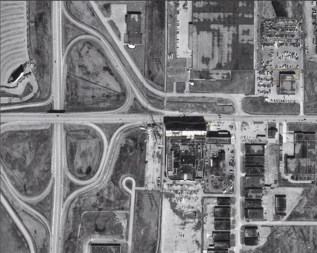
Above: continuing south along the hydro corridor, the view just north of Dixon Road, c.1969. Try as I might, I can’t find any evidence that any of the buildings on the far left along Hwy 27 in the image ever had rail sidings.

Dominion Steel Company of Canada Ltd. (DOSCO)

Above 1957 images from the Panda Associates fonds of the Canadian Architecural Archives, via the University of Calgary (source)

Again, another big Canadian player in the steel manufacturing business for heavy industry. Plant built in 1957 with two rail sidings, site shut down in 1995. Not too much activity at the site until the late 2000’s, presently the Toronto Congress Centre north building.

Status: past customer, now the Toronto Congress Centre

Chrysler

Information here was a bit harder to find, but from what I’ve found it appears this building was originally built and owned by Chrysler. I’m not aware of any automotive assembly plants in the area, and it doesn’t appear to have the rail infrastructure in place for automobile loading/unloading into railcars, so it was probably a distribution warehouse or satellite manufacturing plant (making parts and components to ship to final assembly plants). It became a Sears warehouse (furniture/mattresses) in the 80’s/90’s, and is presently the Toronto Congress Centre’s south building, in use for conventions and public events. For those who remember, in the past it was where the annual March model RR shows of the late 90’s/early 2000’s put on by CARM (The Canadian Ass. of Model RR’ers) were held.

Status: past customer, now the Toronto Congress Centre

Saving the Best for Last: Ontario Hydro / HEPC

But the neatest thing was at the south end of the Highbury Industrial Lead: the spur extended south and ended just outside the Ontario Hydro (then known as the Hydro Electric Power Commission (HEPC) of Ontario) Richview Transformer Station, named after the nearby Richview residential area of Toronto.

Rexdale 2 (1969) E+ copy.jpg
Above: At the southmost end of the line was the Ontario Hydro (Hydro Electric Power Commission of Ontario) Richview Transformer Station, nestled just north of Highway 401 and Highway 27. Note the spur curving and ending next to a paved area outside the plant, to help facilitate cranes and other unloading methods.

To do this, the line had to cross Dixon Road at-grade at a level crossing just east of Highway 27, headed through a hotel parking lot (the present day International Plaza Hotel):

Rexdale 2 (1969) E+2v.jpg
Above: level crossing with Dixon Rd. c.1969, with the previously mentioned Chrysler warehouse at the top. The hotel parking, constructed on the hydro corridor, eventually grew to the west of the tracks over time. Typically there’s not much you can do land-use wise with an active hydro corridor, other than farming it or turning it into parking lots. Also note the drive-in movie theatre at the NW corner of Dixon & Hwy 27.

This long stretch of track, with no other customers to the south, existed to deliver large hydro transformers and other supplies by rail to the site. It was common back in the day that most hydro stations and substations were either located by rail lines, or had their own (often lengthy) spurs to inside or just outside of the property. Ontario Hydro’s sprawling transformer facilities in Pickering were probably the source of many of the dimensional  loads delivered.

CN employee timetables noted that 24 hours notice was required to the Metro [Toronto] Roads Department and the Metro Toronto Police (to direct/stop traffic) for movements over the over the track crossing Dixon Road. It is unknown how long this trackage remained intact with level crossing (likely removed in the 1990’s), but the note was still present in the 1990 CN employee timetable. A rail spur crossing a busy Toronto roadway at grade would never be built today, much less one that would see very infrequent service. Photos of any rail movements here are rare, and it would be nice to come upon some one day.

(An additional aerial photo showing the crossing of Dixon Rd. and the end of the spur in 1959 can be seen on the King’s Highway site’s Ontario Highway 401 Photographs page 2 (specifically here, at the top)

Status: past customer, spur removed.

Closing Thoughts

Over time a lot of the sidings have been taken up and the spur has receded, and today it only reaches as far as Belfield Rd. GO Transit (pre-Metrolinx formation) bought the Weston Sub from CN in 2009. A lot of the unused spurs that were left in place have since been taken up, and the sleepy single track mainline with service tracks has been upgraded to 3-4 mainline tracks for expanded GO service and the Union-Pearson Express trains.

Above: some present-day aerials via Google Earth.

But the Highbury trackage is still in regular use by CN (who has switching rights over Metrolinx/GO’s tracks) – a source indicated that CN locals #549 and #559 presently switch the area. A little under half a dozen customers remain that still use rail service. Most of the tracks south of CKF were taken up a few years back, so no customers south of Belfield and Highway 409 get service anymore (but you can still see some disconnected track in place at Thomson Terminals). The leg to Ontario Hydro is but a memory, and easily missed if you didn’t know it ever existed at all.

Posted in Uncategorized | 2 Comments

CN 568764 40′ Boxcar Rebuild w/ 9′ Door

25285bes-CN568764finished.jpg

Background

Even as newer cars with bigger capacities, larger doors and newer features were coming on the scene, the ol’ venerable 40′ boxcar still proved quite useful to CN and CP in the 60’s and 70’s. Among the rebuilds and repurposing efforts were CN’s rebuilds with 9′ doors.

In the mid-60’s or so, CN began rebuilding some of its old fleet of 40′ boxcars with 6′ doors (mainly the 10’6″ height “1944 AAR” cars) with larger 9′ door openings for service hauling commodities such as newsprint rolls and other high class commodity loading. Most were rebuilt and numbered in various groups in the 56xxxx series, with plug door cars typically becoming 57xxxx cars. The larger door was necessary to allow forklifts room to enter the car, and to both support the forklift and larger door, the sills under the doorway were re-enforced with added steel material. Additional gussets were also welded to certain areas around the door sill for added strength. The usual “modernization” features were also added to cars rebuilt: removed roofwalks, cut down A-end ladders (but full height brake wheel and B-end ladders kept), tack boards relocated to lower positions, and grab/handrails on the ends. The cars otherwise kept most of their as-built features such as ends and roofs, that varied from builder to builder and order to order.

Pick a Car, Any Car.

Unlike cars built-new that share the same features, CN often picked and rebuilt cars taken from numerous different groups from different years and builders, resulting in detail variations from car to car in the same rebuilt series (things such as roofs, sills, steps and ends), so it’s best to consult prototype photos, pick a particular car, and do a little research. Sites like Ian Cranstone’s Canadian Freight Cars and Chris van der Heide’s Canadian Freight Car Gallery are a good source of roster data and photos, as well as various freight equipment books such as the Canadian Rail Car Pictorial series.

According to intel gathered for the project, our particular car chosen to model, CN 568764, was rebuilt in October 1972 from a CN 524000-524499 series 40′ boxcar (again, a 10’6″ height AAR 1944 design) built by National Steel Car in 1948 as 524254. It was built with raised panel roofs and “NSC-2” ends (9 horizontal ribs, with 4 vertical ribs going between them, as opposed to earlier NSC-1 ends where the vertical ribs also went over the horizontal ones). It was painted in CN’s standard brown (the darker 1968+ shade) with large “noodle” logo livery, and very likely rebuilt with yellow doors in ’72. But, at some point in time (probably the 80’s) was repainted with standard brown doors, as many newer larger cars were displacing the old 40’ers from newsprint and other high class goods service.

568764 soldered on until retirement sometime in the 90’s, but found reprieve as a storage shed with two other rebuilt 40’ers at the Consumers Glass (originally Dominion Glass, currently Owens Illinois) plant in Brampton Ont. It was marked as D-453 for disposal or scrapping by CN, and hastily restenciled “CGXX” for temporary movement to its new owner.

CGXX-563026-567417-568764-ex-CN-Owens-Illinois-Brampton-DanD.jpg
“CGXX” ex-CN 563026, 567417, and 568764 at Owens Illinois (formerly Consumers Glass) off Hwy 410 & Clark Blvd, shot from the nearby plaza circa 2007. Our car is half-blocked by all that foliage (if only people just trimmed their bush more often…).

I remember as a kid always passing by on Highway 410 the old Toys R’ Us north of Consumers Glass and always seeing those same 3 cars there facing the highway in the same spot. Digging around various aerial imagery sites, the cars appeared there sometime after 1994, but probably well before 2000, the next closest imagery year I could find. The three continued their padded retirement gig until they were cut up for scrap in July 2014 (possibly in order to salvage the rail underneath them from the siding to extend the pullback track nearby, which was extended not too long after).

CGXX-lineup.jpg
Despite being a monolithic overlording big-brother-eqsue data collection and search engine giant, Google is sometimes your friend, and Streetview provided some additional fuzzy yet bush-less reference photos.

Sorting Itself Out.

At some point the idea to model one or all of the three must have popped into my mind, as it would only be fitting, and some brown noodles would be nice to mix with my red, green and brown CP 40’ers.

But the problem was and still is, nobody makes a model of a CN 40′ boxcar rebuilt with 9′ doors. The “closest” (read not very close) you’d get is the Trains Canada/H&D NSC 40′ boxcar with 8′ doors (tooling now owned by Herpa), but it’s not suitable for an earlier car (aside from the tooling being a bit on the crude side, the ends are the different (later) “NSC-3” design, the door is too narrow, no sill re-enforcement, and it has the later NSC bow-tie roof). So, might as well roll one yourself from a better tooled 6′ door car from Intermountain (for Canadian cars, start with their 41899 undecorated kit), or an out-of-production-but-easy-to-find Branchline Blueprint series 40’er (for this version find one with a raised panel roof – for others, a diagonal panel roof. But both of those and the NSC bow-tie roof are available on request from Intermountain, and will fit both the BL or IM cars). Sylvan Scale Models made resin castings of all the NSC boxcar ends (NSC-1, NSC-2, NSC-3), and their end are still available through Yarmouth Model Works , who acquired the Sylvan freight car parts line.

The 9′ Youngstown doors are a bit more tricky. If you want a quick and easy build, use Kadee part #2245 (9 ft Youngstown Door with narrow border), which has cast-on tack boards close to the right place for CN cars (but not exact, and you’d still need to shave them off if they were relocated to the body on your prototype like on our build). Another source of a suitable door (this time without tack boards) can be found among the old red-box Walthers Waffle-Side 50′ boxcar kits, which had a few 9′ door types included. Since we had some spare Accurail 10′ doors kicking around, it was elected to shorten them to 9′ for a few of these CN rebuilds (note that we need the earlier style ‘ Youngstown door with the narrow side strips/borders, and not the later style with the thicker ones like Kadee #2246 has).

After acquiring a few unbuilt Branchline kits and building some with regular IDE ends (that come with the kit), some Sylvan ends were sourced and work on 568764 began.

Let’s Dig In:

24966bes-CN529153_Branchline_Rebuilt_CN568764.jpg
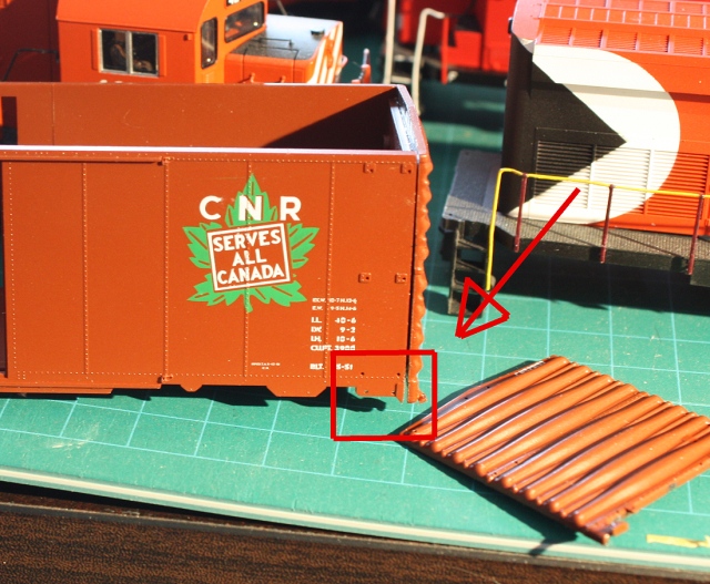
Ironically enough, the car sacrificed was…an old CN kit. Talk about prototypical (don’t worry, I kept and built up two of the five CN kits acquired – the other three were sacrificial lambs).

The ends and doors were put into the parts bin, and the Branchline body and roof were given a strip-bath in 99% isopropyl alcohol in a sealed container (sealed – important!), followed by some scrubbing with an old toothbrush an hour or two later, and repeated re-dunking as needed. Happily, Branchline paint is typically very thin, so stripping them isn’t a problem – any trace amounts of paint can usually be wiped clean with a paper towel dipped in 99%, or persuaded out of corners with a small wooden toothpick. The parts however are much more fragile, so it’s best not to try to strip them as scrubbing to remove the paint may cause damage (there’s so little paint on them it doesn’t really matter).

The Doors:

The important modifications begin at the door. Begin by carefully cutting off the door locking latches on both sides of the doorway, and the door stops at the ends of the door tracks, leaving them intact and setting them aside to reapply later. Next, carefully chisel away the door stop sill on both sides (the vertical strip on the left side of the doorway).

Now grab your Accurail 10′ door (if you’re using a Kadee or Walthers door you can skip the cutting up part). Ideally you want a door without any tack boards on it, but they can be chiseled off later if need be, or left on (they are close to where the tack boards were on rebuilds, but some had them relocated off the door later to facilitate a door push plate). Start by chiseling, sanding or carving off the raised indents on the backs of the Accurail doors to ensure a flush fit with the body later. Then, carefully cut the vertical riveted sides off both sides of each door, and set them aside. Next, cut half a scale foot of door out of each side (shortening the door by a foot but keeping the door handle hardware in the middle) and sand the sides smooth and level. Now would be a good time to chisel off any tack boards or door hardware you don’t want. Clean up and glue the removed riveted sides back to both sides of the door, and add a very thin strip of 0.020″ styrene to the right side of the door, and presto, you have a new 9′ door.

25006bs-CN568764AccurailChoppedDoors.jpg
The door on the right just had its riveted side strips trimmed off. The door on the left shows the roughly half scale foot trimmed off next. The cast-on tack boards could be left in place for rebuilt cars, or carved off and replaced with Branchline parts from the kit.

Before applying the door, snap the roof onto the body and make sure it’s centered – you can use the roof rib locations and side panels of the body to help judge the how centered the doors are when you glue them on. Check again to make sure the back of the door is smooth for a flush fit with the body, apply some plastic cement glue to the back of the door by the sides, carefully stick door on, make sure it’s centered, and let the glue dry (a small clamp or elastic bands may be required to hold the doors until the glue dries. Next, run a bead of glue along the inside of the doorway, making sure to get the top and bottom edges (a toothpick helps to apply in tight spots).

Now, use thin strips of 0.020″ sheet styrene to add a new door stop on the left side of the door. Then, extend the door tracks with 0.020″ styrene cut to match the existing ones (about 4 scale feet on the right side of the body, with small bits added on the top & bottom of the door where it meets the new door stop). I applied some Squadron putty to the door track joints and sanded them to blend in the extensions.

24375s-SillRebuild.jpg
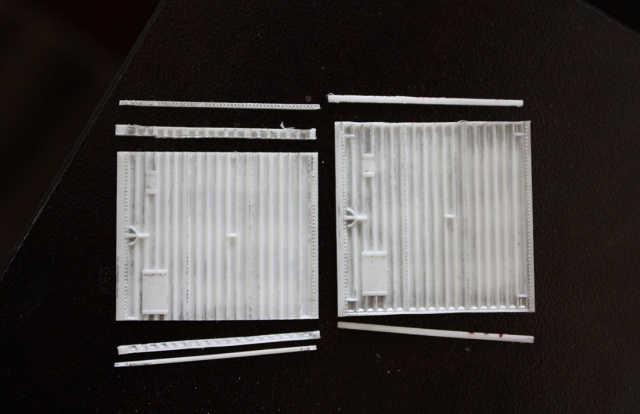
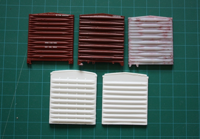
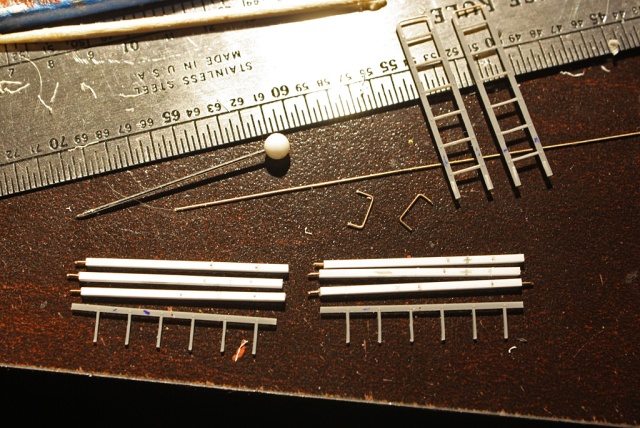
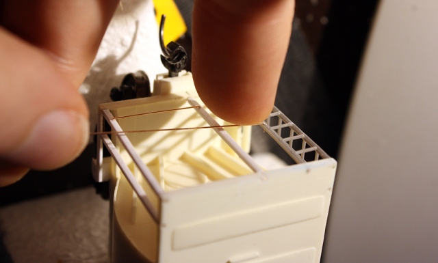
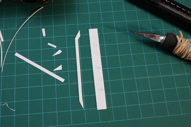
Slicing, dicing, and making julienne fries: working from prototype photos, the new re-enforced door sills were cut from thin sheet styrene. Of note, one end is shorter due to the door track, with a small extra bit extending over the top of the door track that needs to be cut and added on that side.

The door sills were scratchbuilt from 0.010″ sheet styrene according to photos. They’re roughly 18.5 scale feet long, and 1.25 scale feet high. Once glued on, they were re-enforced from the back with more styrene so as not to flex when the car is picked up from the middle. The horizontal notches were made with a sharp pin tool. Small gussets were often welded around the sill area for extra support, and two each side were fabricated from styrene and added to the sill to the bottom left of the door

25023bes-CN568764_Built.jpg
The stripped car with basic sills and doors applied, with some of the door framing and track extensions added on the left. Yet to be done in this photo are extending the door tracks on the longer end (right side), and adding door hardware. Adding the new ends will be covered in the next section.

Once the glue is all dry on the doors, you can start adding the door hardware including tack boards, push plates, and the small wire lugs/door grabs (one at each corner of the door, and one horizontally in the middle, made from brass wire) can be drilled and installed now. There’s typically four door “slider tabs”, one at each corner of the door (made from thin styrene squares). Also reapply the door locking latches carved off in the beginning to the new door stop.

On 60’s-70’s rebuilt cars, the tack boards were typically located on the door in the low position. On some cars including 568764 that underwent an 80’s overhaul (and often lost their yellow doors), the tack boards were relocated to the body just to the left of the doors, and a forklift push plate was installed in the middle of the door (modeled with two 0.010″ pieces of styrene in a “V” configuration in the gap, with a small square added in the middle). Our car in question also appears to have had some door frame re-enforcing added too, with 4 thin tabs on each side of the door (thin 0.010″ styrene squares). Some overhauled cars also had their door levers removed, for reasons unknown.

The End(s), and Roof.

Once the Sylvan NSC-2 ends arrived in the mail from Yarmouth (thanks Pierre!), they were given a wash in Sylvan’s resin prep to clean any casting residue off (others use Dawn dish soap). The ends were initially designed for cars without roof overhangs, so the top needs to be shortened to fit under the overhanging roof.

Dan Talking About Boring Things Again: Boxcar Ends 101:

25293bes-BoxcarEnds.jpg

Take your seats class, welcome to BXC 101 – Introduction to Boxcar Ends. Going from top left to right, first is an older style Dreadnaught end liberated from a LL Proto 2000 50′ boxcar, a design often found on some of the older AAR 1937 design cars. Note the 10 thin ribs (rib count could vary sometimes). Next to is is a brown “Improved Dreadnaught End” (IDE) taken from the kit we’re using. Note the 8 “rolling pin” style ribs (typically 4 divided onto 2 panels). The top rib could vary from a rectangular bar, to a full rib as shown, to a narrower rib. On the top right is an Intermountain IDE, with the narrower top rib usually found on Canadian cars.

On the bottom are the Sylvan resin ends – the NSC-2 (part DP-0038), which has 9 ribs divided on 3 panels, with 4 vertical ribs running through them. And the NSC-3 end (part DP-0039), which typically had 9 ribs on 3 panels with no vertical ribs. A variation of the NSC-3 end found on some Eastern Car Co cars had 8 ribs split on two panels instead of 9 ribs on three. Also, Kaslo makes a later version of the NSC-3 end with boxier ribs for later built 50′ cars.

The most common ends were the IDE and the NSC-3. The earlier NSC-1 end (not pictured) is similar to the NSC-2, but with the vertical ribs bending around the horizontal ones instead, like on this old CN 475xxx series 40’er:
32155es - Former CN 47578x boxcar NSC-1 A-end, blt 1938 at P.jpg
There’s a ribbed joke in all of this, but that’s low-hanging fruit.

With that aside, on to adding the resin ends.

Cement glue is no bueno with resin, so in comes the cyanoacrylate adhesive (CA) to secure the ends to the body. Both smooth surfaces were roughed up with some light sanding for better adhesion. After some trial and error, I found the best method was to enlarge the existing tooling holes on the ends of the body, drilling a few more, and “tacking” the resin end on with a bit of CA glue in the middle (this makes it easier to re-position, and remove if positioned incorrectly without damaging the ends). Once I was happy with the placement, I put a bit of CA on an x-acto knife blade and carefully slipped it along the edge to glue the corners down, and then applied CA from the inside through the enlarged tooling holes to finalize the marriage of resin and plastic.

Working from photos collected of CN cars with NSC-2 ends, holes were drilled on the ends for all the bits that need to be applied, including the brake wheel and rigging, end ladders, grab irons, hand railings, and the two lugs at the top from the torched-off roofwalk supports (much of which came from the kit). As both the Intermountain and Branchline cars don’t have the two side body grabs tooled so that one grab bracket of each rests on the end’s corner side, all the grab holes were filled in and new ones drilled a touch closer to the ends, as well as two on the edges of the new resin ends.

25142+43bs-CN568764_EndsBuilt.jpg
The new detailed ends, with Tichy ladders and Branchline parts applied in newly drilled holes. Some wire was used to fabricate the various grab irons, railings and cut levers. As well, note how the two grabs on the sides of the car now rest on the edge of the ends. Lower tack boards are typical of rebuilt or overhauled cars.

If you have a Branchline car, turn your attention to where the stirrup steps mount on the sill tabs. Some cars were built with sill tabs, others had them retrofitted to that style when rebuilt, others didn’t have them and instead had ladder-mounted stirrups and a square one dropping from the “left” of the body below the two grabs. Consult prototype photos to determine which style your car had, but the sharp jagged point on each of them should be shaved off. I applied the Branchline stirrups now, as they are difficult to install after the ladders.

24966bes-BoxcarStepSills.jpg
This area right here, the stirrup step sills at all 4 corners of the car. It varied on CN cars, but less so on CP ones. Shave that raised pointed area off, and if you’re using the stock Branchline ends, you’ll have to shave the junque off the bottom corners of the ends as well.

Ladders ladders ladders: If you use the Intermountain kit (41899 is your guy), it comes with 8-rug “Canadian style” ladders that you can use (may have to cut the bottom stirrup off depending on prototype). If you get a Branchline kit it’ll come with 7-rug ladders, but certain roads that had them will have 8-rug ladders included. The BL kit has two wide (for the sides) and two narrow (for the ends) ladders, but none of the Canadian cars had the narrow end ladders.  You can use the wider ladders to do the B-end tall ladders and use aftermarket Tichy 3033 ladders to do the chopped-down A-end ladders, or just Tichys all around like what I did (some people prefer the finer Kaslo etched ladders) . The B-end ladders were spliced with one extra rug to get 8, while the A-end ladders were cut down down according to photos (typically 4 rugs). One can drill holes and glue them on by the lugs on the ladders, or shave the lugs off and glue the ladders on flat. Note, some earlier cars (like CN 568764) had one less rug at the bottom of both end ladders, and a grab where the bottom rug would be. All had the lower stirrups on the end ladders (that used to be attached to the bottom of the ladder) removed when rebuilt though.

Dan Talking About More Boring Things Again: Boxcar Roofs 102:

25294bs-BoxcarRoofs.jpg

Welcome class, to BXC 102 – Introduction to Boxcar Roofs. 40’er roof styles varied over the years from order to order and manufacturer to manufacturer.  Starting on the left is a flat-panel roof, often found on early AAR 1937 cars. Next on the red CP 298008 is the typical raised-panel roof, which our build had. Next to that is a CN mystery car (!!!???) with an also common diagonal panel roof. And on the end is our CP 58777 newsprint kitbash with the PS-1 or “bow tie” roof style that Pullman-Standard used their cars, and that NSC used on their later builds. Note that roofwalks (wood vs grated) varied over the years, as did the style of that corner B-end grab when the roofwalk was removed. A good source of the latter three roofs is Intermountain’s parts department.

The Branchline kit’s stock raised-panel roof was used. The one real modification needed on the roof, aside from carving off the end supports at the edge, is fabricating the new “L” shaped grab from wire and its two bar mounts from styrene strip. Normally the bars would be suspended from the roof, but I figured it would be too fragile a setup to replicate, so compromised and glued them to the top of the roof.

Now’s a good time to go ahead and add the underframe brake rigging details, glue on the coupler boxes, or swap them with some Kadee or Sergent boxes (drill and tap for 2-56 screws). Also, small eyebolts can be drilled and mounted on the ends for the cut levers, which were bent from wire and installed at each end according to photos. There were a few different cut lever mounting variations (again, pull out those prototype photos and eyeball ’em).

25141bs-CN568764_Built.jpg
With all that boring stuff done, if you’re still following along and reading this, you should have a car that looks like this sitting in front of you.

Paint Shoppe and Decalling

Once the body was given a light soap wash and rinse to get rid of any hand oils from handling, the car was given a coat of primer, and then a few coats of a custom mix of brown, based on the Proto 1000 CN newsprint cars. It was a mix of TLT CP (SOO) Bright Red and Model Master acrylic Gloss Black. Then followed some Model Master Semi-Gloss Clear in preparation for decalling.

25177s-CN568764firstcoat.jpg
First coat, the very bright Halogen shop lights make it appear a bit lighter.
25176bs-CN568764firstcoat.jpg
The ends look nicer painted, n’est-ce pas? (Mais oui!)

The car was decalled with the “CN Smoothside Boxcars and Vans 1961-1990 – HO Scale” decal set drawn up by Sean Steele and printed by Canuck Models in 2017. The decal film is rather fragile, so it’s best to apply them with just water and (carefully) do the Microsol and pat-down routine. Applying the decals with Microset as one normally would can make them more fragile and susceptible to breaking.

People have their own decalling workflows, but the best lettering technique I’ve found with these is to work from top-down: after studying photos for proper placement, apply the top “Canadian National”, then the separator line, then just the “CN” to help placemark the datablock below. Then the sideways “H” datablock, making sure everything is lined up and parallel, and then filling in the roadnumber and any capacity/load data in the datablock.

25269bs-CN568764decalling.jpg
It can haz decals. Le Francais side applied, with the number and datablock waiting to be filled in with more data. CN was a crown corp at the time, so the lettering was bilingual. Pay attention to which side of your car is the french (Quebecois?) side, and which side is en anglais. 

To get the correct number, each digit was applied one at a time and carefully lined up according to photos. The datablock was also altered to try to match the capacity data I could find on that car and similar cars, as well as the build date and last shop date (the shop date on the prototype was blanked out, so I gave it an early 80’s date. CN and CP seemed to switch from listing the individual shop’s two letter code to just “CN” or “CP” for everything in the early 80’s, so the car was lettered appropriately).

25103s-CN567417decalling.jpg
Here’s CN mystery car (!!!???) 567417, currently in the shop, when it was getting its decal treatment. Each of those little digits on my digits were cut out to get the exact build date and shop date desired. Easily applied with the wet tip of a fine paintbush brush. The CUFT capacity was also waiting to get its “88” for 3880.

Once all the itty bitty data was sorted out, I cut out and applied the large CN noodle logos. Because of the thin decal film, you can apply the noodle decals as-is and they should be fine after the usual Microsol+bubble pop+pat-down technique. Since I’m a stickler for decal film, I employed the glutton-for-punishment method of cutting all the excess film in the logos out, and then applying them. This was not only difficult and time-consuming, but resulted in the noodles tearing easily and having to go on in 3-4 pieces each. But all the breaks were lined up and vanished once it was all Microsol’ed down – and no film in between to deal with!

25054es-CN440601noodledecalling.jpg
G()_(@W#%$$(UT%Jrg$I)34T$TM456GdsFJE%GI)GB NOODLE DECAL APPLICATION on car 440601, also getting noodles at the time.

Any little decal bits such as the door lettering decals, reflective frame dots, and COTS block (optional – check photos.  Yes, it was actually applied over the rivet strip on some cars including this one) was then sorted out. Once the decaling was dry, the car given two coats of Model Master Semi-Gloss Clear with a touch of water to thin it out, to simulate a somewhat clean and fresh finish, as this would have been a recently shopped car and will mingle freely with earlier yellow-doors.

Extra Bits:

The stock Branchline trucks were given a coat of the body colour (as was common CN practice when repainting) and applied. The wheels were first checked with the ol’ NMRA gauge, and the axle points were cleaned up with a sharp x-acto knife (often flash or casting imperfections can cause BL wheels to roll poorly). Couplers used were Kadee #58’s in the stock box, which was glued on the body and drilled and tapped for 2-56 screws. The kit’s air line/hoses had their mounts chopped off, and were glued to the side of the coupler box a la prototype (I glued the most inside part to the couple box, allowing the hose and outer part closer to the coupler to flex away if the coupler should come in contact with it, instead of damaging or snapping the fragile hoses off). Oh, and the push plate was painted yellow too – that’s important.

25286bes-CN568764finished.jpg
Showing off its raised panel roof, 9′ wide door, and NSC-2 ribbed ends.

25283es-CN568764finished.jpg
A-end detail. Daylight was running short when taken, so the lighting in some photos might be a bit  inconsistent.
25287bes-CN568764finished.jpg
NSC-2 B-end with brake end detail.
25290bs-CN568764-440601finished.jpg
A “sister” car acquired at the same time was redone as CN 440601, a 40’er rebuilt with roof-hatches, and equipped with Kadee National B1 trucks. Perhaps it may show up in a future post, along with that CN mystery car (!!!???)…

Posted in Uncategorized | 3 Comments

CPAA 205021 – 60′ Greenville Auto Parts Boxcar


IMG_4947bs - CPAA 205021.jpg
Trade agreement with another country? Ship those cross-border auto parts with ease, in one of these!

Background:

The cars in question were Canadian Pacific’s first group of 60′ auto parts boxcars, built in March 1966 by the Greenville Steel Company, to help facilitate the Canada-US Auto Pact automotive trade agreement. They were originally lettered as CP cars, but later changed to CPAA for “International service”. The first block 205000-205025 were outfitted for auto engine service, and the second block of 205026-205034 for transmission service, both equipped with cushion underframes and large twin plug doors. CP would purchase subsequent 60′ boxcars for auto parts service, but from other American builders such as Thrall, Pullman Standard and ACF. Other additions to the auto parts fleet included both purpose-built 50′ boxcars and repurposed 50′ boxcars as well as larger 86′ hi-cube boxes. The last of the Greenville cars from this group were retired in 2007/2008. It’s hard to pin down which plants they served, but photos showing them at St. Therese would suggest at least some went to/from the GM plant there, that CP switched.

There’s a good selection of prototype photos of this car series on the Canadian Freight Car Gallery, as well as a photo one in its mid-late 70’s appearance in Canadian Rail Car Pictorial Vol. 3 Pt.1 (CP 50’+ boxcars).

Starting Point:

The starting point for the model is the “Greenville 60 Foot Box Car (Double Plug Door)” made by Robin’s Rails Inc, although it is the same tooling as the Con-Cor car. They made both double and single door models, but CP only had double door prototypes. This model old and out of production (released sometime in the 1980’s, a parts package in mine was stamped for July 1985) but not too hard to come by via the usual channels. The detail level isn’t up to par with modern models – the door detail is a bit flat, the rivets are a bit on the heavy side as are the ladder parts, and there was apparently a measurement error that resulted in them being tooled a bit shorter than they should be (half a foot-ish). The also underframe reflects prototype cars built with the 42″ truck bolster spacing, rather than the 46″ spacing CP’s cars were built with.

But despite those flaws, it’s really the only starting point for this particular prototype. Purchased by about a dozen railroads, these were the earlier Greenville 60′ cars built starting in the mid-60’s that cubed out around 6000 cuft, not to be confused with other offerings from them such as their later 7100 cuft cars of the 70’s, and the very large 86′ hi-cubes. There are a couple of pros with the car that make upgrading it easier. Not too much can be done about the minor height issue or all the rivets, but the underframe rails are separate from the underframe floor, making it a matter of a few cuts to rearrange the frame part to modify the bolster spacing. And, all the ladder and brake detail on the body are separately applied parts, making it easy to chuck them for finer or more detailed replacements.

It Begins: Body Modifications

As always, start off by stripping the existing paint off the body (I got a case of the lazy at the time, and elected to just sand most of the lettering off with 800 grit sandpaper and merely paint over it – it was a brown GTW car and was going to be brown anyway – but for most decorated cars stripping is the way to go).

The sills of the car were extended about 3.25 scale inches to reflect the longer truck bolster spacing. 0.020″ sheet styrene was cut to the proper parallelogram shape, re-enforced flush with some extra 0.020″ styrene from the rear, patched and sanded smooth to match the rest of the body.

The old ladders were too much on the chunky side, and chucked back in the box. Working from photos, Tichy ladders (from part #3033) were cut up into new 4-rug ladders for 6 of the corners. The two full-height B-end corner ladders near the brakewheel were made by splicing ladder bits into longer 8-rug ladders (the Tichy ladders are only 7-rungs), by drilling two small holes in them and using thin wire to fasten sections together. Note that if you’re doing a car with roofwalk intact, you’ll want two full height ladders on the opposite A-end corner as well. Holes were then marked and drilled on the body sides corresponding with the mounting pins on the backs of the ladders, and they were glued on the body (or one can just cut off the ladder pins and glue them right on).

24538bs.jpg
New Tichy ladders, end platforms, tack boards, and sill extensions to match the new longer wheelbase.

The stirrup steps that come with the kit are rather fine Detail Associates parts so they were used. Holes were drilled into the sill from the bottom and they were glued on with CA. At the same time, holes were drilled next to them and a U-ring (for any cable pulling, bent from 0.015″ wire) was installed near each stirrup.

I’m modeling a car without the roofwalk, so it was left off the kit (it too was on the chunky side). Instead, holes were drilled and two small Detail Associates NBW (nut-bolt-washer) parts were installed at the tops of the ends where the bracing was torched off, and a rooftop B-end grab by the tall ladders was scratchbuilt from bits of styrene and 0.015″ wire. I also nipped the corners of the top skinny rib at each end, as this one didn’t go to the edges of the car on the prototype.

CP left the brake rigging on the B-end mounted high (but at some point at least on one car had it relocated to the low position. It was scratchbuilt using a Kadee modern brakewheel, brake housing from a Proto 2000 gondola kit, small length of chain and 0.015″ wire. Styrene bits were used at the top of the housing to fill the mounting gap. The small brakewheel walkway was made from etched grating leftover from a Kadee kit, with flat staples bent into shape for the supports.

24576-75es-CPAA205021_Ends.jpg
Extra end bits: ladders, stirrups, end platforms, end grab, NBW castings for roofwalk supports, new brake wheel, platform, top B-end grab, and some styrene bits on the lower ends.

A small short grab was bent from wire and added between the 4th and 5th ribs on each end (slightly offset on the B-end), and Intermountain tack boards were added to the ends as well as the doors, going by prototype photos. To finish off the body detailing, end platforms were added to the body just above the couplers by using some leftover roofwalk grating from the parts box, and small bits of styrene were added to the ends below to simulate the area around the cushioned underframe.

24370bes2-CPAA205000-series.jpg
At “Shop Desk Yard” with some other specimens in for work.

Underframe Mods:

The underframe needs to be modified to get the longer truck bolster spacing CP’s cars had. Unfortunately I didn’t take any photos of this process, but with the frame part of the underframe separate from the floor:

On each, make a cut on the inside of the bolster mount right where it and the long section of the frame join. You should have two T-shaped bits with the bolster mount and coupler mount attached, as well as the long piece of the frame that goes between them (put this piece aside).

On both the T-shaped bits, measure along the frame 2.5 scale feet from the edge of the bolster, and make a cut. This should give you two sets of smaller T-shaped pieces (with the bolster mounts), and two pieces of frame with the end coupler pockets.

Now, (don’t glue anything down until the following modification to the floor!) reassemble the frame onto the floor, but just flip the T-pieces 180 degrees so the bolster mounts are closer to the ends of the car (remember to file and trim all splices to all the pieces join flush and straight with each other) and you’ll have the longer 46’3″ bolster spacing. Drill and tap for long 2-56 screws.

(Note: the Atlas ACF 60′ auto parts boxcar has about the same spacing, so one could aquire and modify an underframe from one of those to fit as an alternative. You’ll need to chop the ends down a touch as the Atlas underframe is longer on the ends).

IMG_4962bes.jpg
TL:DR? Here’s the completed, modified underframe. Basically you just need to cut and flip 180 degrees the section between the two compass tips, into the orientation shown here. Also shown is the coupler box screw mod, and the messy underframe Dremel job (see below)

You may want to modify the end pieces of the frame that have the coupler mounts on them, as normally the couplers will need to be added before you glue those outer frame pieces to the floor. What I did was glue blocks of styrene between the frame rails right after the coupler mounts, drilled and tapped them and the floor for 2-56 screws, thereby making the frame ends removable for adding/changing couplers. You could also just upgrade this part with better detailed cushioned draft gear from Moloco. Kadee #58’s were mounted in the stock coupler boxes, which aren’t the most detailed but functional.

The stock Athearn trucks were chucked for a set of Proto 2000 36″ trucks, with a Kadee grey washer on the bolster to level them up a bit. Relevant prototype note time: CP’s Greenville cars were rated as 263,000 lb (263k) cars and had 100-ton trucks (With 36″ wheels), other roads may have had identical cars with the same specs and trucks, or rated 220k with 70-ton trucks (and 33″ wheels) instead. Handy cheat: to work this out, simply add the Load Limit and Light Weight data values on the car below the roadnumber.

One important underframe mod that was required due to upgrading to prototypical 36″ wheels: equipping the model with said 36″ wheels brought the car to a proper looking ride height, but caused the wheel flanges to rub against beams cast into the underframe floor. One could just add a few more washers, but that would bring the ride height too high. The solution was to get a Dremel with a cutting wheel and grind off those frame members, and make small indentations in the floor to avoid any flange rubbing  (see that underframe photo posted above). Be careful not to go too deep as you may grind through the floor (a la that white bit of styrene).

IMG_4963es.jpg
Mounting the P2K 36″ wheels and trucks, and the piping added near the ends. One small modification I like to do to cars that might rock or wobble too much is add a small bit of spring from a pen on the inside of one screw, so that when it’s screwed in (not all the way) the spring dampens any body wobbling, while still allowing the truck to turn and rock freely. A spring on one truck is all that’s needed; the other truck can be left to rock unsprung.

Other underframe mods include adding trainline piping along opposite sides at the A- and B-ends by the trucks. This was fabricated from more 0.015″ wire. The stock underframe details aren’t the best and could benefit from better detailed parts if one so chooses to upgrade them with added brake rigging. And of course, don’t forget to add weight. The stock weight is a bit light, so one may want to add a few peel and stick weights to bring the car up to NMRA specs.

Paint Shoppe:

This order of cars from Greenville (GS) and CP’s first order of 205500-series 60′ Pullman Standard (PS) auto parts boxcars were the only two groups with large “Canadian Pacific” script lettering, underneath it “International of Maine division”. Apparently (at least on the PS cars) the scheme weathered poorly so cars often had ratty lettering painted over. I’d assume the same for the GS cars, but looking at a photo of a patched one in the mid-late 1970’s the base paint was still in relatively good shape. Perhaps it was just a general order by CP for all PS and GS cars with the large lettering to have it patched because of this, even if the GS paint job was more durable (many photos of the GS cars in the 90’s and early 2000’s show them still in their original albeit ratty and tagged paint, while photos of many of the PS cars show them having been repainted into different CP variations). It’s notable that two GS cars, CPAA 205002 and 205003, did get repainted in the late 90’s into the newly introduced CPR livery with the new beaver logos.

At any rate, I decided to do a mid-70’s patched car, so the paint would have been in decent shape and the patch job relatively fresh. One can apply the large CP script if one wants to model a relatively new car (I’m sure a few unpatched cars managed to evade patching, as some PS cars did) or if one wants to fade it in from under a patch (for ratty cars later in life).

After cleaning the body, it was sprayed with a primer coat and ready for painting. The era I model would have had any patches still fresh with no lettering visible underneath, so forgoing the script decals is easiest here (if one was to do a fade-through on a ratty car, apply the lettering after the body colour but before the patches, and lightly sand the patched area with 800-1200 grit sandpaper to expose the lettering under it). Since there were no decals to apply to patch over, I did the reverse since it was easier: I painted the whole car the “patch colour”, and then covered over the patch areas with painter’s tape, like so:

24782bs.jpg

Then I tweaked the boxcar brown paint mix I was using to be a slightly lighter more yellow colour (to simulate faded roughly 10-year old paint), and then sprayed the body colour over the entire car.

24783bs.jpg

Now, when you remove the masks over the patched lettering, you’ll have two freshly painted areas visible on a slightly faded car.

24784bes.jpg
Look carefully, it’s there.

The roof was then masked off and sprayed silver.

After all the patching was sorted out*** (see addendum below), I reapplied the masking over the patched areas again and applied a few layers of a black wash by airbrush, focusing on the roof, rivet lines on the sides, and the lower area of the car to give it a slightly used but not abused or filthy look. Now when you remove the masks over the patched lettering, you’ll have two freshly painted areas on a slightly faded and car (I sprayed the patched areas with a light coat of black wash as well).

Picking the right colour can be a headache, as often a colour from the jar is good for a new car, but not one that’s either faded or seen some service. For the body colour used, I used a custom mix of brown made starting from Model Master rust, MM black, with some MM International orange and some TLT CP/SOO red. For the patched areas I used a similar mix, but a bit more red & black added to slightly shift the colour. The roof was sprayed with a mix of Tamiya aluminum silver, with some grey and flat white added to the mix. The black wash was a drop of Model Master semi-gloss black in about half an airbrush cup of water (one can vary this for greater or letter effect, or apply more layers). Once all the painting was done, the car was clear coated in preparation for decalling.

***Painting addendum time:

There were a few minor issues with the primer coat I applied sticking to the smooth body properly (it wasn’t a primer per se, but Model Master Rust, as it covered the base paint fine and the final coats were going to be brown anyway), so when I was applying some of the CDS decals the painting tape I used to help keep the decal paper on ended up pulling up some of the paint, and as this was an older CDS set the decal paper stuck to and pulled up a few bits of paint as well! Also, while masking the patchout at varous stages the same thing happened with the painter’s tape. Patchy model = conundrum time. Rather than strip the whole thing to re-detail and re-paint, I painstakingly repaired the small areas of paint that were pulled out by the tape, and took more caution. Normally this isn’t a problem with a good purpose-made primer like Tamiya Fine Surface Primer (bulletproof as a primer coat on plastic and resin), or even most acrylic paints I’ve used as primer in the past such as TLT and Pollyscale greys, but for some reason the MM coat wasn’t up to snuff.

The repair process I used was basically removing any loose flaking and sanding the edges of the “paint hole” with 800 grit sandpaper, then cleaned the area of any sanded residue, and sprayed a good coat of the brown body colour in the general area of the paint hole. After it dried, I sanded more to blend the edges in, cleaned the surface and sprayed again. Once happy, I gave the area a light black wash to match the rest of the car and shot on clear in preparation for decalling. Time consuming, but it saved stripping the car and starting back at square one. Ironically enough, when applying CDS decals again over these patched areas they were fine and never pulled up with the decal paper or tape – perhaps sanding the smooth body helped paint adhesion.

Decalling:

With the painting sorted out, it was time to break out CDS set 498 (CP 60′ Auto parts boxcar) which provided the reporting marks, numbers, capacity data, and some door lettering. The dimensional data and some other door lettering came from Microscale 87-2 (Data, gothic) set. The dimensional data block on both my CDS sets weren’t usable – some of the smaller lettering was missing or had flaked off the dry transfer sheet, a common problem with some of the smaller lettering bits on CDS sets.

IMG_4935bs.jpg
CP typically had rather spartan lettering on most of their leased and American-built cars. This car a good example and there’s nothing really fancy here, although lettering fonts tended to vary depending on the builder.

Additional bits were AEI tags from an old Rapido sheet, and the “206” block lettering which came from a custom set (but could probably be put together numbers from with a generic decal set). The seemingly random codes such as that were door or spotting location codes, indicating to crews where a particular car should be spotted at a plant or warehouse. On more recent shots of these cars you’re likely to see a number of them that have been patched over and resprayed in different spots on the car, as assignments or locations changed. Also, one would often find a white square with assignment or return to/home shop details (e.g. Return to GM Oshawa).

Once all the decals are applied, Microsol’ed, dry, and/or rubbed down, spray the car the clear coat of choice to seal, and apply more weathering if desired. Now’s a good time to add any extra fragile bits such as air lines and cut levers to the ends (I still need to get some for this one).

Foto Time:

IMG_4939bs

IMG_4942bs.jpg
IMG_4948bs.jpg
IMG_4938bs - CPAA 205021.jpg
Ready to ship some new engines to auto plants for installation in that 60’s boat, 70’s rustbucket, 80’s jalopy or 90’s winter beater.

Posted in Uncategorized | 1 Comment